IM 12D7B3-E-E
3-1 Installation and wiring
3. INSTALLATION AND WIRING
3-1. Installation and dimensions
3-1-1. Installation site
The EXA transmitter is weatherproof and can be installed inside or outside. It should, however, be installed
as close as possible to the sensor to avoid long cable runs between sensor and transmitter. In any case,
the cable length should not exceed 60 meters (200 feet). Select an installation site where:
● Mechanical vibrations and shocks are negligible
● No relay/power switches are in the direct environment
● Access is possible to the cable glands (see figure 3-1)
● The transmitter is not mounted in direct sunlight or severe weather conditions
● Maintenance procedures are possible (avoiding corrosive environments)
The ambient temperature and humidity of the installation environment must be within the limits of the
instrument specifications. (See chapter 2).
3-1-2. Mounting methods
Refer to figures 3-2 and 3-3. Note that the EXA transmitter has universal mounting capabilities:
● Panel mounting using two (2) self-tapping screws
● Surface mounting on a plate (using bolts from the back)
● Wall mounting on a bracket (for example, on a solid wall)
● Pipe mounting using a bracket on a horizontal or vertical pipe (maximum pipe diameter 50 mm)
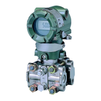
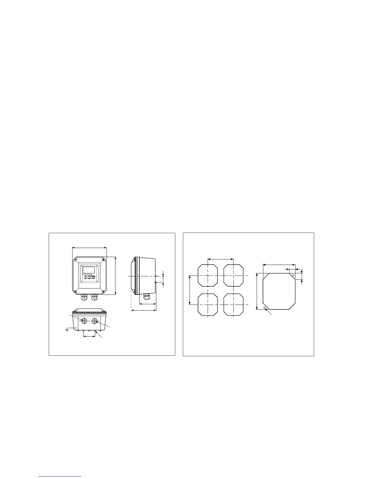
Fig. 3-2. Panel mounting diagramFig. 3-1. Housing dimensions and layout of
glands

 Loading...