IM 12D7B3-E-E
Installation and wiring 3-6
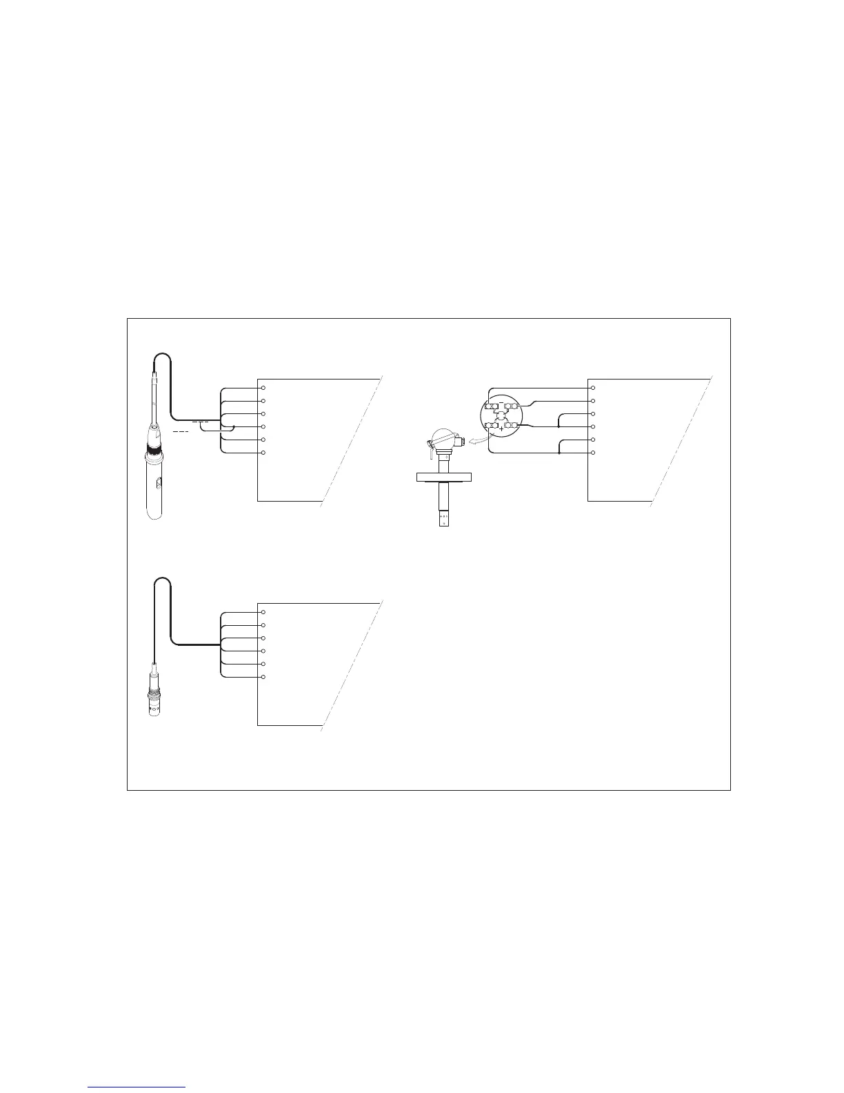
3-5. Sensor wiring
Refer to figure 3-9, which includes drawings that outline sensor wiring.
The EXA SC202 can be used with a wide range of commercially available sensor types if provided with
shielded cables, both from Yokogawa and other manufacturers. The sensor systems from Yokogawa fall
into two categories, the ones that use fixed cables and the ones with separate cables.
To connect sensors with fixed cables, simply match the terminal numbers in the instrument with the
identification numbers on the cable ends.
The separate sensors and the WU40-LHhh cables are also numbered, but the numbers do not always
match with the terminal numbers in the instrument. Figure 3-9 indicates how to connect the different sensor
types.
11 TEMPERATURE
12 TEMPERATURE
13 CELL
14 CELL
15 CELL
16 CELL
CONDUCTIVITY / RESISTIVITY TRANSMITTER
SEPARATE SENSORS WITH WU40-LH . . CABLE
11 TEMPERATURE
12 TEMPERATURE
13 OUTER ELECTROD
E
14 OUTER ELECTROD
E
15 INNER ELECTRODE
16 INNER ELECTRODE
SC4A... SENSORS WITH INTEGRATED CABLE
RED
11 TEMPERATURE
12 TEMPERATURE
13 OUTER ELECTROD
E
14 OUTER ELECTROD
E
15 INNER ELECTROD
E
16 INNER ELECTROD
E
YELLOW / GREEN
BROW
N
BROWN
1
2
1
2
SX42-SX . . - . F SENSORS

 Loading...