IM 12D7B3-E-E
2-1 Specifications
2. GENERAL SPECIFICATIONS
2-1. Specifications
A. Input specifications : Two or four electrodes measurement
with square wave excitation. Cell
constants from 0.008 to 50 cm-1
WU40 sensor cable up to 20m. Up
to 60m total using BA10 junction box
and WF10 extension cable
B. Detection method : Frequency, read-pulse position and
reference voltage are dynamically
optimized.
C. Input ranges
- Conductivity : 0.000 µS/cm to 1999 mS/cm at
25 °C (77 °F) reference temperature.
Minimum : 0.2 µS x C at process temperature
(underrange 0.000 µS/cm).
Maximum : 500 mS x C at process temperature
(overrange 550 mS x C).
- Resistivity : 0.000
∧U - 999 ] U/C at 25 °C
(77 °F) reference temperature.
Minimum : 0.002
∧U/C at process temperature
(underrange 0.000 k
Ω x cm).
Maximum : 5
] U/C at process temperature
(overrange 999 M
Ω x cm).
- Temperature
Pt1000 : -20 to +250 °C (0 - 500 °F)
Pt100 and Ni100 : -20 to +200 °C (0 - 400 °F)
8K55 NTC : -10 to +120 °C (10 - 250 °F)
Pb36 NTC : -20 to +120 °C (0 - 250 °F)
D. Output Span
- Conductivity : - min 0.01µS/cm
: - max. 1999 mS/cm. (max 90% zero
suppression)
- Resistivity : - min 0.001k
Ωxcm
: - max. 999
] U x cm. (max 90% zero
suppression)
- Temperature : Dependent on temp. sensor type:
Sensor type min. max.
Pt1000 25 °C (50 °F) 250 °C (500 °F)
Pt100, Ni100 25 °C (50 °F) 200 °C (400 °F)
Pb36 NTC, 8k55 NTC 25 °C (50 °F) 100 °C (200 °F)
The instrument is user programmable
for linear or non-linear conductivity
ranges.
E. Transmission Signal
: Isolated output of 4-20 mA DC .
Maximum load 425
Ω.
Burn up (22 mA) or Burn down
(3.9 mA) or pulse of 22mA to signal
failure. See Fig.2-1 and 2-2.
F. Temperature compensation
: Automatic, for temperature ranges
mentioned under C (inputs).
- Reference temp. : programmable from 0 to 100 °C or
30 - 210 °F (default 25 °C).
G. Compensation algorithm
-NaCl : According IEC 746-3 NaCl tables
(default).
-T.C. : Two independent user programmable
temperature coefficients, from -0.00%
to 3.50% per °C (°F) by adjustment or
calibration.
- Matrix : : Conductivity function of concen-
tration and temperature. Choice out
of 5 preprogrammed matrixes and a
25-point user-programmable matrix.
H. Serial Communication
: Bi-directional according to HART
digital communication super imposed
on the 4-20mA signal.
I. Logbook : Software record of important events
and diagnostic data. Available through
HART interface.
J. Display : Custom liquid crystal display, with a
main display of 3
1
/
2
digits 12.5 mm
high. Message display of 6 alpha-
numeric characters, 7 mm high.
Warning flags and units (mS/cm,
kΩ.cm, µS/cm and MΩ.cm) as
appropriate.
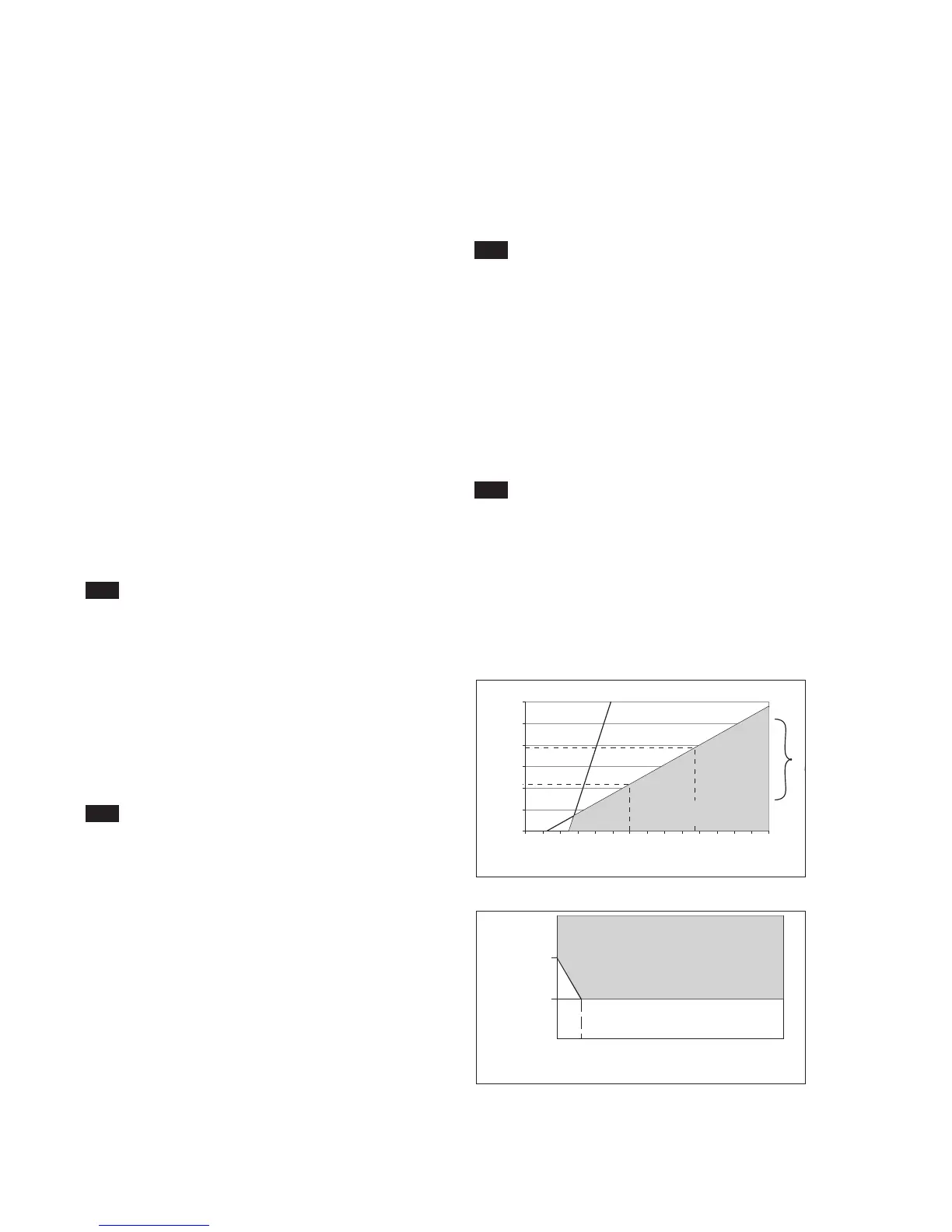
K. Power supply : Nominal 24 volt DC loop powered
system.
SC202G ; up to 40 volts
SC202S : up to 31.5 volts
Note: The transmitter contains a switched
power supply. The transmitter requires
a minimum Power voltage in order to
work correctly, which is dependant on
the load. Please refer to figures 2-1
and 2-2 for the correct power supply.
Fig. 2-1. Supply voltage/ load diagram
Fig. 2-2. Minimum terminal voltage at the SC202

 Loading...