IM 12D07J01-10E-E
30
Table 5: Defintion of WU10 cable, WE10 cable, WU40 cable and WF10 cable
VP connector Cable wire color SC analyser Signal
WU10-V-D-** / WE10-H-D-** Terminal # description
A Core brown coax 15 Ui (inner electrode)
B Shield brown coax 16 Ii (inner electrode
C Core white coax 13 Uo (outer electrode)
D Shield white coax 14 I0 (outer electrode)
E Red 11 Temperature
F Blue 12 Temperature
G Yellow N/A
H Green N/A
Note: For the WU40 and WF10 cable the labelled wires must be connected to the corresponding
terminal # of the SC analyser.
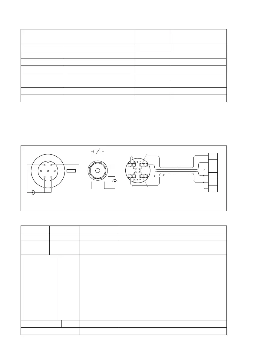
The SX42 flanged models are provided with a connection box. The cable used to connect these
sensors to the analyser has to be a high temperature shielded cable. This cable is not supplied by
Yokogawa. The wiring diagram of the flanged models is given in fig.32.
11
12
13
14
15
16
(12)
(11)
(15)
(13)
Shield
Use WF10 cable or a customer
specific high temperature cable
Interconnect #15 with #16,
and #13 with #14 in analyser
11
12
13
15
16
14
temp.
element
CELL
A
C
D
E
F
G
H
B
Variopin
connector
Amphenol
connector
Fig. 32 SX42 threaded models connector (top view)
Model Suffix Code Option code Description
SX42 High temp. conductivity sensor with Pt1000 sensor
-SX24 Cell constant 0.1/cm
-SX34 Cell constant 0.01/cm
-BS ISO 7/1-R1 screw thread, plug-socket conn.
-BV
1)
ISO 7/1-R1 screw thread, VarioPin conn.
with SENCOM ID-chip 1)
-NS 1-11½ NPT screw thread, plug-socket conn.
-NV
1)
1-11½ NPT screw thread, VarioPin conn.
with SENCOM ID-chip 1)
-DF DN50-PN63 EN flange
-EF DN50-PN40 EN flange
-AF 2” 600 LBS ANSI flange
Style *A Always *A style
Option N/A
Note: Suffix -BV and -NV not ATEX/IECEx certified.
 Loading...