IM 05P02D41-11EN page 10/14
5. Switching between AUTO and MAN
AUTOandMANswitching canbeperformedusing anyofthefollowing: (1)MODE
key,(2)Contactinput,(3)Contactinput,and(4)Communication.
ThefollowingshowsanexampleofswitchingusingtheMODEkey.
WhenAUTOandMANswitchingfunctionis assignedtothe contactinput,andthe
contactinputisON,theswitchingbykeyoperationcannotbeperformed.
Fordetails,seeUser’sManual.
Displays ”MODE MAN” in AUTO mode.
Displays ”MODE AUTO” in MAN mode.
Press MODE key several times.
Show the Operation Display.
4.
MAN lamp is lit in MAN mode.
Press the SET/ENTER key.
WhenAUTOisswitchedintoMAN,thecontroloutputvalueinAUTOmodeisheld.
Thecontrollercanbeoperatedmanuallyfromtheholdvalue.
Ifthemanualpresetoutputisset (MPONparameter≠ OFF),thecontrollercanbe
operatedmanuallyfromthearbitraryoutputvalue(MPO1toMPO5parameters).
6.
Manipulating Control Output in Manual Mode
NOTE
Inmanualmode,control outputismanipulatedbyoperatingthekeys(thevalueis
changedusingtheUp/Downarrowkeys,thenoutputtedasitis).
Evenifthe SET/ENTERkeyisnotpressed,thecontroloutputvaluechangesac-
cordingtothedisplayedvalue.
Instopmode(whentheRSTlampislit),controloutputcannotbemanipulated.
MAN lamp is lit.
Up arrow key: increases control output.
Down arrow key: decreases control output.
In Position proportional control:
Up arrow key; opens the valve.
Down arrow key; closes the valve.
Output; only while pressing a key.
OUT; valve opening (0-100%)
Output manipulation in Position proportional control
is not restricted from output limiters (OH, OL).
Manual operation in Heating/cooling control
Symbol of cooling side
Program pattern (PTNO.) number
Symbol of heating side
Heating-side control output
Cooling-side control output
Uparrowkey: concurrentlydecreasescooling-sidecontroloutputandincreases
heating-sidecontroloutput.
Downarrowkey:concurrentlyincreasescooling-sidecontroloutputanddecreases
heating-sidecontroloutput.
(Eithernoneofthe heating-sideandcooling-sideoutputs arepresented,orboth of
themarepresentedaccordingtothedeadbandsetting.)
DB=24.8
Dead band: Operation parameter DB
Control computation output Control computation output
12.40-12.4
Manipulated output change
when a dead band is positive (+)
Actual output (%)
100
DB= -24.8
12.40-12.4
Manipulated output change
when a dead band is negative (-)
100
Cooling-side
manipulated output
Heating-side
Heating-side
manipulated output
Cooling-side
7.
Enabling/Disabling Hold Mode of Program Operation
Enabling/disablingholdmodeofprogramoperationcan beperformedduringpro-
gramoperationusinganyofthefollowing:(1)MODEkey,(2)Parameter,(3)Contact
input,and(4)Communication.
ThefollowingshowsanexampleofswitchingusingtheMODEkey.
Show the Operation Display.
Press the MODE key.
The number of segments included
in the selected program pattern.
The segment number for which
operation is in progress.
The figure below is displayed while the right
arrow key hold down.
Displays ”HOLD ON” in PROG mode.
Displays ”HOLD OFF” in HOLD mode.
HLD lamp is lit in HOLD mode.
Press the SET/ENTER key.
The parameter HOLD (Pause/cancel release
of program operation) is displayed (during
program operation.)
1.
2.
3.
4.
Show the Operation Display.
Press the MODE key.
The number of segments included
in the selected program pattern.
The segment number for which
operation is in progress.
The figure below is displayed while the right
arrow key hold down.
Displays ”HOLD ON” in PROG mode.
Displays ”HOLD OFF” in HOLD mode.
HLD lamp is lit in HOLD mode.
Press the SET/ENTER key.
The parameter HOLD (Pause/cancel release
of program operation) is displayed (during
program operation.)
Otheroperatingproceduresfordisablingtheholdmode:
(1)PresstheRUNkeyfor1 secondduringhold-mode operation.Inthis case,the
controllerresumesprogramoperation.
(2)Executethe“Advance“functionduringhold-modeoperation.Inthiscase,the
segmentisadvanced.
8.
Changing Program Setpoints when in Hold Mode
Thefollowingoperating procedureschangesaprogramsetpointofsoaksegment
duringHold-modeoperation.
Theprogramoperation isstartedwhen releasingtheHoldafterchanging thepro-
gramsetpoint.
.
Set program operation in hold mode.
.
.
Blinks during the change.
Blinks during the change.
Press the SET/ENTER key.
Press the SET/ENTER key.
Press the Up/Down arrow keys to display the required setpoint.
9.
Executing “Advance” Function
“Advance”canbeperformedduringprogramoperationusinganyofthefollowing:(1)
MODEkey,(2)Parameter,(3)Contactinput,and(4)Communication.
ThefollowingshowsanexampleofswitchingusingtheMODEkey.
Whenexecutingthe“Advance”functionduringhold-modeoperation,theholdmodeisdisabled.
4.
The segment is advanced.
Press the SET/ENTER key.
Show the Operation Display.
Press the MODE key.
The ADV (Advance of segment) is displayed (during
program operation.)
10.
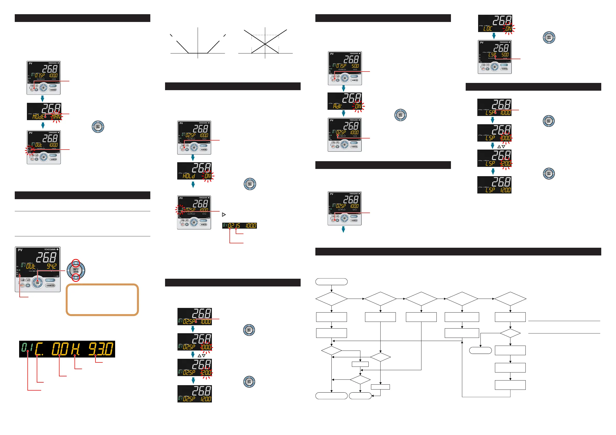
Switching to Local-mode (LOCAL) Operation
Switchingtolocal-modecanbeperformedusinganyofthefollowing:
(1)MODEkey(userfunctionkey),(2)Parameter,(3)Contactinput,and(4)Communication.
ThefollowingshowsanexampleofswitchingusingtheMODEkey.
1.
2.
3.
4.
“LSP” is displayed when
in local-mode operation.
Press the SET/ENTER key.
Show the Operation Display.
Press the MODE key several times.
The LOC (local operation) is displayed.
■
Remedies if Power Failure Occurs
during Operations
• Instantaneouspowerfailurewithin20ms.
Apowerfailureis notdetected.Normal
operation continues.
• Powerfailureforlessthanabout5seconds,
orforabout5secondsormore.
Affectsthe"settings"and"operationsta-
tus."
Fordetails,seeUser'sManual.
NOTE
Writedownthesettings ofparametersfor a
repairrequest.
■FortheErrorsatPowerOn
and the Errors during Op-
eration, see “Parameters”
in this manual.
.
“LSP” is displayed when
in local-mode operation.
Press the SET/ENTER key.
Show the Operation Display.
Press the MODE key several times.
The LOC (local operation) is displayed.
11.
Changing Setpoints during Local-mode Operation
Thefollowingoperatingprocedureschangessetpointsduringlocal-modeoperation.
.
.
.
“LSP” is displayed when in local-mode operation.
Press the SET/ENTER key.
Press the SET/ENTER key.
Blinks during the change.
Blinks during the change.
Press the Up/Down arrow keys to display the required setpoint.
■TroubleshootingFlow
IftheOperationDisplaydoesnotappearafterturningonthecontroller’spower,checktheproceduresinthefollowingowchart.
Ifaproblemappearstobecomplicated,contactoursalesrepresentatives.
defective?
Contact us for repair.
Problem solved.
No communication
capability
Completely
inactive?
Yes
Yes
Yes
No
No
No
Key
operation
failure?
Yes
No
Yes
Check wiring of the
power terminals.
Check the key lock
setting.
Display
failure?
*
Yes
No
Turn off power, and
then turn it on again.
I/O signal
failure?
Yes
No
Check the
supply voltage.
Check the
specifications and polarity
of connected devices .
Check the communication-
related parameters.
Check the specifications
of communication
devices.
Check the
communication wiring.
Communication
failure?
No
With
communi-
cation?
Yes
Yes
Normal?
Is the
key locked?
Check the specifications
of the controller.
Yes
No
Correct?
Correct the error(s).
Cancel the setting.
Check the I/O specifications
of the controller.
* The LCD (a liquid crystal display) is used for
a display portion of this product.
The LCD has a characteristic that the display action
becomes late at the low temperature.
Additionally, the luminance and contrast degradation
are caused due to aged deterioration.
However, the control function is not affected.
12. Troubleshooting

 Loading...


