IM 05P02D41-11EN page 11/14
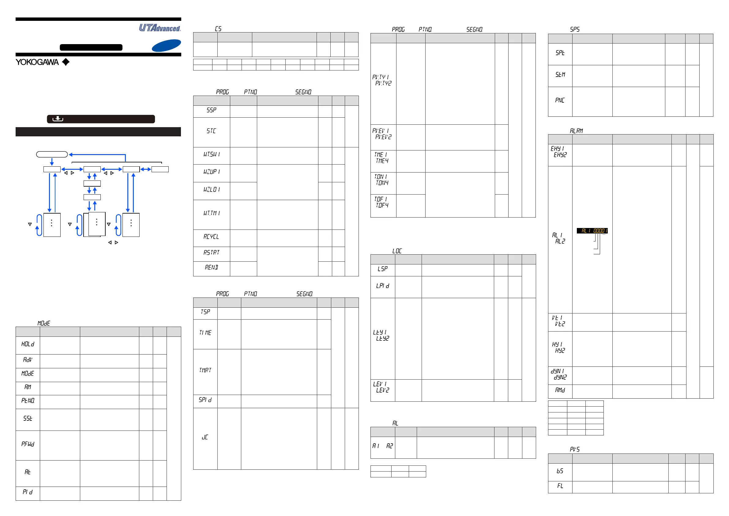
Operation Parameters / Program Parameters
HolddownthePARAMETERkeyfor3secondstomovefromtheOperationDisplaytotheOper-
ation
ParameterSettingDisplay.PresstheDISPLAYkeyoncetoreturntotheOperationDisplay.
Menu
DISPLAY or DISP key
key
key key
key
key
The parameter groups can be switched using , keys.
Operation Dsipaly
Parameter
Parameter
Parameter
Parameter
Parameter
Parameter
END
PROG
PTNO.
SEGNO.
END
Menu END
END
Menu Display
and Parameter
Setting Display
are changed in a
circular pattern.
Hold down PARAMETER or PARA for 3 sec.
SET/ENTER key
1 to 2 (4)
SET/ENTER key
SET/ENTER
key
PARAMETER
or PARA key
PARAMETER
or PARA key
PARAMETER
or PARA key
1 to 20
Parameter
Parameter
END
Move to the Setup Parameter Setting Display:
Hold down the PARAMETER or PARA key and the Left arrow key simultaneously for 3 sec.
Operation for Setting
· Toselecttheparametersettingdisplayedastheinitialvalue,presstheDownarrow
keytomovetothenextparameter.
·
Tochangeand settheparametersetting,presstheSET/ENTERkeytostart thesetpoint
blinking.Theblinkingstateallowsyoutomakechanges(settingmode).UsetheUp/Down/Left/
Rightarrowkeystochangethesetpoint.PresstheSET/ENTERkeytoregisterthesetting.
Notethattherearesomeparameterswhicharenotdisplayeddependingonthemodel
andsufxcodes,controltype(CNT),etc.Theparametersforprofessionalsettingmode
(LEVL:PRO)arenotdescribedinthismanual.SeeUser’sManual.
■ Operation Mode
Menusymbol:
(MODE)
Parameter
symbol
Name of Parameter Setting Range
Initial
value
User
setting
Display
level
(HOLD)
Pause/cancelreleaseof
programoperation
Displayduringprogramoperation.
ON:Pause
OFF:Cancelrelease(Programopera-
tionrestart)
OFF
EASY
(ADV)
Advanceofsegment
Displayduringprogramoperation.
Setas“ADV=ON”toadvancefromthe
currentsegmenttothenextsegment.
OFF
(MODE)
Operationmode
RESET:Stopofprogramoperation
PROG:Startofprogramoperation
LOCAL:Startoflocal-modeoperation
RESET
(A.M)
AUTO/MANswitch
AUTO:Automaticmode
MAN:Manualmode
MAN
(PTNO.)
Programpatternnumber
selection
0:Notselectprogrampattern
1to2(4whentheoption“/AP”is
specied.)
0
(SST)
Start-of-programseg-
mentnumber
1to20(40whentheoption“/AP”is
specied.)
Thesettingvaluereturnsto“1”when
theprogramoperation(PROG)
changesintoRESETorLOCAL.
1
(P.FWD)
Fast-forwardingof
programoperation
1:Normal,2:Twice,5:Fivetimes,
10:Tentimes
*
Usethisfunctionwhencheckingthe
programpatternsetting.OnlySegment
timeandTimeeventcanbefaster.
*Theoperationreturnstothenormal
speedafterfast-forwarding.
1
(AT)
AUTO-tuningswitch
OFF:Disable
1to4:Performauto-tuning.Tuning
resultisstoredinthespecied
numberedPID.
R:TuningresultisstoredinthePID
forreferencedeviation.
OFF
(PID)
PIDnumber
ThePIDgroupnumberbeingselected
is displayed.
1to4,R:PIDgroupforreferencedeviation.
1
■ SELECT Parameter
Menusymbol: (CS)
Parameter
symbol
Name of Parameter Setting Range
Initial
value
User
setting
Display
level
Registered
parameter
symbol
SELECTparameter
10to19
Settingrangeofaregisteredparameter.
Fordetails,seeUser'sManual.
–
Table
below
EASY
Parameter n=10 n=11 n=12 n=13 n=14 n=15 n=16 n=17 n=18 n=19
CSn
FortheregistrationofSELECTparameters,seeUser'sManual.
■ Program Setting Parameter
Menusymbol:( PROG> PTNO.(=01to02(04)> SEGNO.(=00))
Parameter symbol
Name of
Parameter
Setting Range
Initial
value
User
setting
Display
level
(SSP)
Startingtarget
setpoint
0.0to100.0%ofPVinputrange(EU)
(Settingrange:P.RLtoP.RH)
P.RL
EASY
(STC)
Start code
SSP:Programoperationbeginswith
thestartingtargetsetpoint.
RAMP:Ramp-prioritizedPVstart
TIME:Time-prioritizedPVstart
LSP:Local-modestart
*
STC=TIMEcannotbeselectedwhen
theparameterSEG.TisTM.RT.
SSP
(WT.SW1)
Waitfunction
ON/OFF
OFF:Disable
ON:Enable
OFF
STD
(WZ.UP1)
Upper-side
waitzone
0.0to10.0%ofPVinputrange(EU)
0.5%
ofPV
input
range
(WZ.LO1)
Lower-side
waitzone
0.5%
ofPV
input
range
(WT.TM1)
Waittime
OFF:Nofunction
0.00to999.59(“hour.minute”or“min-
ute.second”)
*Availableonlyforthewaittimeatthe
segmentswitching.
*
UsetheparameterTMUtosetthetime
unit.(Commonintheinstrument.)
OFF
(R.CYCL)
Numberof
repeat cycles
0to999,CONT(limitlessnumberof
times)
0
(R.STRT)
Repeatcycle
startsegment
number
1to20(40)
1≤R.STRT≤R.END≤20(40)
1
(R.END)
Repeatcycle
endsegment
number
1
■ Program Setting Parameter
Menusymbol:( PROG> PTNO.(=01to02(04))> SEGNO.(=01to20(40))
Parameter
symbol
Name of
Parameter
Setting Range
Initial
value
User
setting
Display
level
(TSP)
Finaltarget
setpoint
0.0to100.0%ofPVinputrange(EU)(Setting
range:P.RLtoP.RH)
P.RL
See
"Pro-
gram-
ming"
in this
manual.
EASY
(TIME)
Segmenttime
setting
-:Unregistered
0.00to999.59(“hour.minute”or“minute.second”)
*
SettingavailablefortheparameterSEG.T=TIME.
*UsetheparameterTMUtosetthetimeunit.
(Commonintheinstrument.)
*Ifthesettingis0.00,TSPchangesinstepwise
after one control period.
-
(TM.RT)
Segment
ramp-rate
setting
-:Unregistered
Ramp:0.0to100.0%ofPVinputrangespan
(EUS)/1houror1minute
Soak:0.00to999.59(“hour.minute”or“minute.second”)
*
SettingavailablefortheparameterSEG.T=TM.RT
*UsetheparameterTMUtosetthetimeunit.
(Commonintheinstrument.)
Per1hour:TMU=HH.MM,Per1minute:TMU=MM.SS
*Ifitissetto0.0%oftheinputrangespan,or
thesegmenttime0.00,theprogrammovesto
thenextsegmentafteronecontrolperiod.
-
(S.PID)
SegmentPID
numberselection
1 to 4
*PIDnumbercanbesetwhentheparameter“ZON=0.”
1
(JC)
Junction code
CONT:Switchingforcontinuation.
HOLD:Hold-onswitching(thecontrollerholdsthe
end-of-segmentsetpointwhenthesegmentis
completed,toperformcontrol).
LOCAL:
Local-modeswitching(thecontrollerswitchestoa
localsetpointwhenthesegmentiscompleted).
W.SW:
Waitduringswitchingbetweensegments.
W.IV:Waitwithinasegmentinterval.
W.SL:Segmentswitching(thecontrollerswitches
toalocalsetpointwhenthesegmentiscom-
pletedafterrelease.)
PLK.1toPLK.4:Linkedtopatterns1to4.
INS.:Allowsasegmenttobeaddedtotheendof
aspeciedsegment.
DEL.:Allowsaspeciedsegmenttobedeleted.
CONT
See
"Pro-
gram-
ming"
in this
manual.
STD
■ Program Setting Parameter
Menusymbol:( PROG> PTNO.(=1to02(04))> SEGNO.(=01to20(40))Continued.
Parameter
symbol
Name of
Parameter
Setting Range
Initial
value
User
setting
Display
level
to
(PV.TY1to
PV.TY2)
PVevent-1to-2
type
OFF:Disable
(Energized)
1:PVhighlimit,2:PVlowlimit,
3:SPhighlimit,4:SPlowlimit,
5:Deviationhighlimit,
6:Deviationlowlimit,
7:Deviationhighandlowlimits,
8:
Deviationwithinhighandlowlimits,
9:TargetSPhighlimit,
10:TargetSPlowlimit,
11:TargetSPdeviationhighlimit,
12:TargetSPdeviationlowlimit,
13:
TargetSPdeviationhighandlowlimits,
14:
TargetSPdeviationwithinhighandlowlimits,
15:OUThighlimit,16:OUTlowlimit,
17:Cooling-sideOUThighlimit,
18:Cooling-sideOUTlowlimit
*Add100for"de-energized".
Forexample,whenthePVhighlimitisde-
energized,thesettingis101.
OFF
See
"Pro-
gram-
ming"
in this
manual.
STD
to
(PV.EV1to
PV.EV2)
PVevent-1to-2
setpoint
SetadisplayvalueofsetpointofPValarm,SP
alarm,deviationalarm,oroutputalarm.
-19999to30000(Setavaluewithintheinput
range.)
Decimalpointpositiondependsontheinput
type.
0
to
(TME1to
TME4)
Start condition of
timeevent1to4
ON:StartONstate
OFF:StartOFFstate
OFF
to
(T.ON1to
T.ON4)
Ontimeoftime
event1to4
-:Unregistered
0.01to999.59(“hour.minute”or“minute.
second”)
*Availableonlywithinthesegmenttime.
*OFFwhentheoperationmodeischanged
tothemodeexcepttheprogramoperation.
*
UsetheparameterTMUtosetthetimeunit.
(Commonintheinstrument.)
-
to
(T.OF1to
T.OF4)
Offtimeoftime
event1to4
-
PVeventandTimeeventareavailableonlyduringtheprogramoperation.
PVeventparametersaredisplayedinorderofPVevent1(PV.TY1,PV.EV1),PVevent2.
TimeeventparametersaredisplayedinorderofTimeevent1(TME1,T.ON1,T.OF1),Timeevent2,Timeevent3,
and so on.
■ Local Setting Parameter
Menusymbol: (LOC)
Parameter
symbol
Name of
Parameter
Setting Range
Initial
value
User
setting
Display
level
(LSP)
Localtarget
setpoint
0.0to100.0%ofPVinputrange(EU)(Setting
range:P.RLtoP.RH)
P.RL
EASY
(L.PID)
PIDnumberse-
lectionforlocal-
mode operation
SetaPIDgroupnumbertouse.
1 to 4
*
AvailableonlyfortheL.PIDwhenZON=0or5.
*Ifsetto“LocalPIDselection,”localPIDisse-
lectedirrespectiveoftheoperationmodes.
1
to
(L.TY1to
L.TY2)
Localevent-1to
-2type
OFF:Disable
(Energized)
1:PVhighlimit,2:PVlowlimit,
3:SPhighlimit,4:SPlowlimit,
5:Deviationhighlimit,
6:Deviationlowlimit,
7:Deviationhighandlowlimits,
8:
Deviationwithinhighandlowlimits,
9:TargetSPhighlimit,
10:TargetSPlowlimit,
11:TargetSPdeviationhighlimit,
12:TargetSPdeviationlowlimit,
13:
TargetSPdeviationhighandlowlimits,
14:
TargetSPdeviationwithinhighandlowlimits,
15:OUThighlimit,16:OUTlowlimit,
17:Cooling-sideOUThighlimit,
18:Cooling-sideOUTlowlimit
*Add100for"de-energized".Forexample,
whenthePVhighlimitisde-energized,the
settingis101.
OFF
STD
to
(L.EV1to
L.EV2)
Localevent-1to
-2setpoint
SetadisplayvalueofsetpointofPValarm,SP
alarm,deviationalarm,oroutputalarm.
-19999to30000(Setavaluewithintheinput
range.)
Decimalpointpositiondependsontheinputtype
0
LocaleventparametersaredisplayedinorderofLocalevent1(L.TY1,L.EV1),Localevent2.
■ Alarm Setpoint Setting Parameter
Menusymbol: (AL)
Parameter
symbol
Name of
Parameter
Setting Range
Initial
value
User
setting
Display
level
to
(A1toA2)
Alarm-1to-2
setpoint
Thesealarmsworkirrespectiveoftheoperationmode.
SetadisplayvalueofsetpointofPValarm,SPalarm,
deviationalarm,outputalarm,orvelocityalarm.
-19999to30000(Setavaluewithintheinputrange.)
Decimalpointpositiondependsontheinputtype
0
Table
below
EASY
Usethefollowingtabletorecordalarmsetpoints.
Parameter n=1 n=2
An
■ SP-related Setting Parameter
Menusymbol: (SPS)
Parameter
symbol
Name of Parameter Setting Range Initial value
User
setting
Display
level
(SPT)
SPtrackingselection
Trackingisperformedwhenthe
modechangesfromProgramto
Local.(Thelocalsetpointkeeps
trackoftheprogramsetpoint.)
OFF,ON
OFF
STD
(S.TM)
Startingtimeofprogram
operation
0.00to999.59(“hour.minute”or
“minute.second”(commonuseof
instrument)
*UsetheparameterTMUtoset
the time unit.
0.00
(PNC)
Programpatternnumber
clearance
OFF:Notcleared.
ON:Cleared.(Settheprogramnum-
ber
beforerestartprogramoperation)
*Thecontrollerresets(clears)the
programpatternnumberonthe
operatingdisplayto“0”attheendof
programoperation.
OFF
■ Alarm Function Setting Parameter
Menusymbol: (ALRM)
Parameter
symbol
Name of Parameter Setting Range
Initial
value
User
setting
Display
level
to
(EHY1to
EHY2)
Event-1to-2hysteresis
ThehysteresissetpointofPVeventor
Localeventissettotheparcentage
of0.0to100.0%.
Thesettingvalue(%)isforthePV
inputrangespanoroutputspan.
0.5
Table
below
STD
to
(AL1toAL2)
Alarm-1to-2type
Example:Alarm-1
Stand-by
action
Latch action
Energized/
De-energize
Alarm
type
Thesealarmsworkirrespectiveofthe
operationmode.Seta5-digitvaluein
thefollowingorder.
[Latchaction(0/1/2/3/4)]+[Energized
(0)orDe-energized(1)]+[Without(0)
orWith(1)Stand-byaction]+[Alarm
type:2digits(seebelow)]
Forlatchaction,seeUser'sManual.
AL1:
Latch
action
(0)
Ener-
gized
(0)
Without
Stand-
by
action
(0)
PV
high
limit(01)
AL2:
Latch
action
(0)
Ener-
gized
(0)
Without
Stand-
by
action
(0)
PVlow
limit(02)
EASY
Alarmtype:2digits
00:Disable
01:PVhighlimit
02:PVlowlimit
03:SPhighlimit
04:SPlowlimit
05:Deviationhighlimit
06:Deviationlowlimit
07:Deviationhighandlowlimits
08:
Deviationwithinhighandlowlimits
09:TargetSPhighlimit
10:TargetSPlowlimit
11:TargetSPdeviationhighlimit
12:TargetSPdeviationlowlimit
13:
TargetSPdeviationhighandlowlimits
14:TargetSPdeviationwithinhigh
and low limits
15:OUThighlimit
16:OUTlowlimit
17:Cooling-sideOUThighlimit
18:Cooling-sideOUTlowlimit
19:AnaloginputPVhighlimit
20:AnaloginputPVlowlimit
27:Feedbackinputhighlimit
28:Feedbackinputlowlimit
29:PVvelocity
30:Faultdiagnosis
31:FAIL
to
(VT1toVT2)
PVvelocityalarmtime
setpoint 1 to 2
0.01to99.59(minute.second) 1.00
to
(HY1toHY2)
Alarm-1to-2hysteresis
Setadisplayvalueofsetpointof
hysteresis.
-19999to30000(Setavaluewithin
theinputrange.)
Decimalpointpositiondependsonthe
inputtype.Whenthedecimalpointpo-
sition
fortheinputtypeissetto"1",the
initialvalueofthehysteresisis"1.0".
10
to
(DYN1toDYN2)
Alarm-1to-2On-delay
timer
AnalarmoutputisONwhenthedelay
timerexpiresafterthealarmsetpoint
is reached.
0.00to99.59(minute.second)
0.00
STD
(AMD)
Alarmmode
0:Alwaysactive
1:NotactiveinRESETmode
2:NotactiveinRESETorMANmode
0
Parameter n=1 n=2
EHYn
ALn
VTn
HYn
DYNn
■ PV-related Setting Parameter
Menusymbol: (PVS)
Parameter
symbol
Name of Parameter Setting Range
Initial
value
User
setting
Display
level
(BS)
PVinputbias
-100.0to100.0%ofPVinputrange
span(EUS)
0.0%of
PVinput
range
span
EASY
(FL)
PVinputlter OFF,1to120s OFF
Operation
Guide
Yokogawa Electric Corporation
Parameters
UP35A/UP32A
Program Controller
Operation Guide
For details of the each function, refer to the electronic manual. Manuals can be
downloaded or viewed at the following URL.
Functional
Enhancement
http://www.yokogawa.com/ns/ut/im/
This operation guide describes the functions of parameters briefly. The parameter
symbols listed are in the order shown on the display in each group of menu symbols. In
addition, each parameter table has a “User Setting” column, where you can record your
setpoints when setting them in the controller. The scrolling guide is displayed on
PV display in the Parameter Setting Display. This guide can be turned on/off with the
MODE key.
«Standard Code Model»

 Loading...


