IM 05P02D41-11EN page 5/14
Contents
1. NamesandFunctionsofDisplayParts
2. Setup Procedure
3. QuickSettingFunction(SettingofInputandOutput)
4.
AdjustingValvePositionAutomatically(foraPositionProportionalTypeControllerOnly)
5. SettingAlarmType
6. SettingAlarmSetpoint
1. Names and Functions of Display Parts
(1)
(2)
(8)
(10)
(12)
(11)
9)
2)
10)
11)
12)
(4)
(3)
(5)
(6)
(7)
(8)
(2) + (3) + (4) : Setpoint display
No.ingure Name Description
(1)
PVdisplay
(whiteorred)
DisplaysPV.
Displaysanerrorcodeifanerroroccurs.
DisplaysthescrollingguideintheMenuDisplayandParameter
SettingDisplaywhentheguidedisplayON/OFFissettoON.
(2)
Groupdisplay(pattern
number)(green)
1to4representpatternnumbersintheOperationDisplay.
Displaysagroupnumber(1to4orR)andterminalarea(E1toE4)
intheParameterSettingDisplay.
(3)
Symboldisplay(orange)
Displaysaparametersymbol.
(4) Datadisplay(orange) Displaysaparametersetpointandmenusymbol.
(5)
Bar-graphdisplay
(event,alarm)
(orange)
DisplaystheeventstatusandthesegmentpositionintheOperation
Display.(Defaultvalues:Timeeventstatus,Alarmstatus)
Displayscontroloutputvalue(OUT)andmeasuredinputvalue(PV).
Thedatatobedisplayedcanbesetbytheparameter.
(6)
Eventindicator
(orange)
LitwhenthePVeventsoccur.
Eventdisplayscanbesetbytheparameter.
(7)
Keynavigationindica-
tor(green)
LitorblinkswhentheUp/DownorLeft/Rightarrowkeyoperation
ispossible.
(8)
Parameterdisplaylevel
indicator(green)
Displaysthesettingconditionsoftheparameterdisplaylevelfunc-
tion.
Parameter display level EASY PRO
Easysettingmode Lit Unlit
Standardsettingmode Unlit Unlit
Professionalsettingmode Unlit Lit
(9)
Programmonitor
(green)
(UP35Aonly)
Displaysthestatusofincrement,constancy,anddecrementofthe
programsetpoint.
:Litwhenaprogramsetpointisincreasing.
:Litwhenaprogramsetpointisconstant.
:Litwhenaprogramsetpointisdecreasing.
(10)
Status indicator
(greenandred)
Displaystheoperatingconditionsandcontrolstatus.
Indicator Description
HLD Litwheninholdmode(HLD).
PRG
Litwheninprogrampatternoperationmode
(PRG).LitwhiletheStartingtimeofprogram
operation(S.TM)isavailable.
RST Litwheninresetmode(RST).
MAN
Litwheninmanualmode(MAN).
Blinksduringauto-tuning.
(11) Securityindicator(red) Litifapasswordisset.Thesetupparametersettingsarelocked.
(12)
Ladderoperation
indicator(green)
Litwhiletheladderprogramoperationisexecuted.
(4)
(5)
(1)
(2)
(3)
(4)
No.ingure Name Description
(1)
UP35A:DISPLAYkey
UP32A:DISPkey
UsedtoswitchtheOperationDisplays.
PressthekeyintheOperationDisplaytoswitchtheprovided
OperationDisplays.
PressthekeyintheMenuDisplayorParameterSettingDisplay
toreturntotheOperationDisplay.
(2)
UP35A:
PARAMETER
key
UP32A:PARAkey
Holddownthekeyfor3secondstomovetotheOperation
ParameterSettingDisplay.
HolddownthekeyandtheLeftarrowkeysimultaneouslyfor3
secondstomovetotheSetupParameterSettingDisplay.
PressthekeyintheParameterSettingDisplaytoreturntothe
MenuDisplay.Pressthekeyoncetocanceltheparameterset-
ting(setpointisblinking).
(3)
SET/ENTERkey
Up/Down/Left/Right
arrow keys
SET/ENTERkey
PressthekeyintheMenuDisplaytomovetotheParameter
SettingDisplayoftheMenu.PressthekeyintheParameter
SettingDisplaytotransfertotheparametersettingmode(set-
pointisblinking),andtheparametercanbechanged.
Pressthekeyduringparametersettingmodetoregisterthesetpoint.
Up/Down/Left/Rightarrowkeys
PresstheLeft/RightarrowkeysintheMenuDisplaytoswitch
theDisplays.
PresstheUp/Down/Left/RightarrowkeysintheParameter
SettingDisplaytoswitchtheDisplays.
PresstheUp/Downarrowkeysduringparametersettingmode
(setpointisblinking)tochangeasetpoint.
PresstheLeft/Rightarrowkeysduringparametersettingmode
(setpointisblinking)tomovebetweendigitsaccordingtotheparameter.
(4) Light-loaderinterface
Itisthecommunicationinterfacefortheadaptercableusedwhen
settingandstoringparametersfromaPC.TheLL50AParameter
SettingSoftware(soldseparately)isrequired.
(5)
ForUP35A,
RUNkey
RSTkey
MODEkey
PTNkey
ForUP32A,
RUNkey
MODEkey
RUNkey:PresstheRUNkeyfor1secondwhileanoperation
displayisshownstartstheprogrampatternoperation.
RSTkey:PresstheRSTkeyfor1secondwhileanoperation
displayisshownstopstheprogrampatternoperation.
MODEkey:PresentsadisplayforswitchingbetweentheHOLD,
ADVANCE,PROG,RESET,LOCALandAUTO/MAN.
Inordertochangetheoperationmode,presstheSET/
ENTERkeywhilethesetpointisblinking.
PTNkey:Aprogrampatternnumbercanbeselectedduringthe
operationexcepttheprogrampatternoperation.(The
programpatternnumberdisplayedontheGroupdisplay
blinks.)WhenthePTNkeyispressedwhiletheprogram
patternnumberisblinking,theblinkstops.
Userscanassignfunctionstothekeyusingparameters.
Note: Thecommunicationconnector(maintenanceport)forLL50AParameterSettingSoftwareis
on the top of the unit.
2. Setup Procedure
ThefollowingowchartshowsthesetupprocedureforUP35A/UP32A.
Install and wire a controller.
Monitoring and control of regular operations
Adjust PID using auto-tuning or manually for PID control.
Other setup
Operation
NO
NO NO
YES
YES YES
Set the other parameters as needed.
Programming
Set the program pattern.
PID tuning
Input setup
Output setup
Installation
and wiring
Power ON
Control type setup
Control type setup
Input/output setup
Valve position
adjustment
Use
Quick setting
function?
Position
proportional
type?
Position
proportional
type?
For Position proportional type
3.
Quick Setting Function (Setting of Input and Output)
TheQuicksettingfunctionisafunctiontoeasilysetthebasicfunctionofthecontrol-
ler.
TurnonthecontrollertostarttheQuicksettingfunction.
Thisfunctionallowsyoutoeasilysetthecontroltype,input,andoutput,andquickly
start the control action.
Theitems(parameters)tobesetbyQuicksettingfunctionareasfollows.
(1)Controltype(PIDcontrol,Heating/coolingcontrol,etc.)
(2)Inputfunction(PVinputtype,range,scale(atvoltageinput),etc.)
(3)Outputfunction(controloutputtypeandcycletime)
Afterturningonthecontroller,rstdecidewhetherornottousetheQuicksettingfunction.
Operation in Initial Display
· PresstheSET/ENTERkeywhileYESisdisplayedtostarttheQuicksettingfunction.
· Ifyou changeYES toNOand presstheSET/ENTER key,Operation Displaywill
appearwithoutstartingtheQuicksettingfunction.
Initial Settings
This operation guide describes basic settings and operations of the UP35A/UP32A.
For details of each function, see the electronic manual.
The scrolling guide is displayed on PV display in the Parameter Setting Display.
This guide can be turned on/off with the MODE key.
UP35A/UP32A
Program Controller
Operation Guide
For details of the each function, refer to the electronic manual. M
anuals can be
downloaded or viewed at the following URL.
Functional
Enhancement
http://www.yokogawa.com/ns/ut/im/
«Standard Code Model»
Operation for Setting
· Toselecttheparametersettingdisplayedastheinitialvalue,presstheDownarrow
keytomovetothenextparameter.
· Tochangeandsettheparameter setting,pressthe SET/ENTERkeytostart
thesetpointblinking.Theblinkingstate allowsyoutomake changes(set-
tingmode).Usethe Up/Down/Left/Rightarrowkeysto changethesetpoint.
PresstheSET/ENTERkeytoregisterthesetting.
■ Making Settings Using Quick Setting Function
Example: Setting to PID control, thermocouple type K (range of 0.0 to
500.0
0
C), and current control output
Forthedetailed procedureandswitching ofdisplays,see"FlowofQuickSetting
Function"below.Fortheparameterstoset,seethenextpage.
(1)PresstheSET/ENTERkeywhileYESforQSM(Quicksettingmode)isdisplayed.
(2)Setthecontroltypeparameter(CNT)toPID(PIDcontrol).
(3)SetthePVinputtypeparameter(IN)toK1(-270.0to1370.0
0
C).
(4)SetthePVinputunitparameter(UNIT)toC(DegreeCelsius).
(5)SetthemaximumvalueofPVinputrangeparameter(RH)to500.0.
(6)SettheminimumvalueofPVinputrangeparameter(RL)to0.0.
(7)Settheoutputtypeselectionparameter(OT)toOUTterminals(current).
(8)Finally,EXITisdisplayed.ChangeNOtoYESandpresstheSET/ENTERkeyto
completethesetup.OperationDisplayappears.
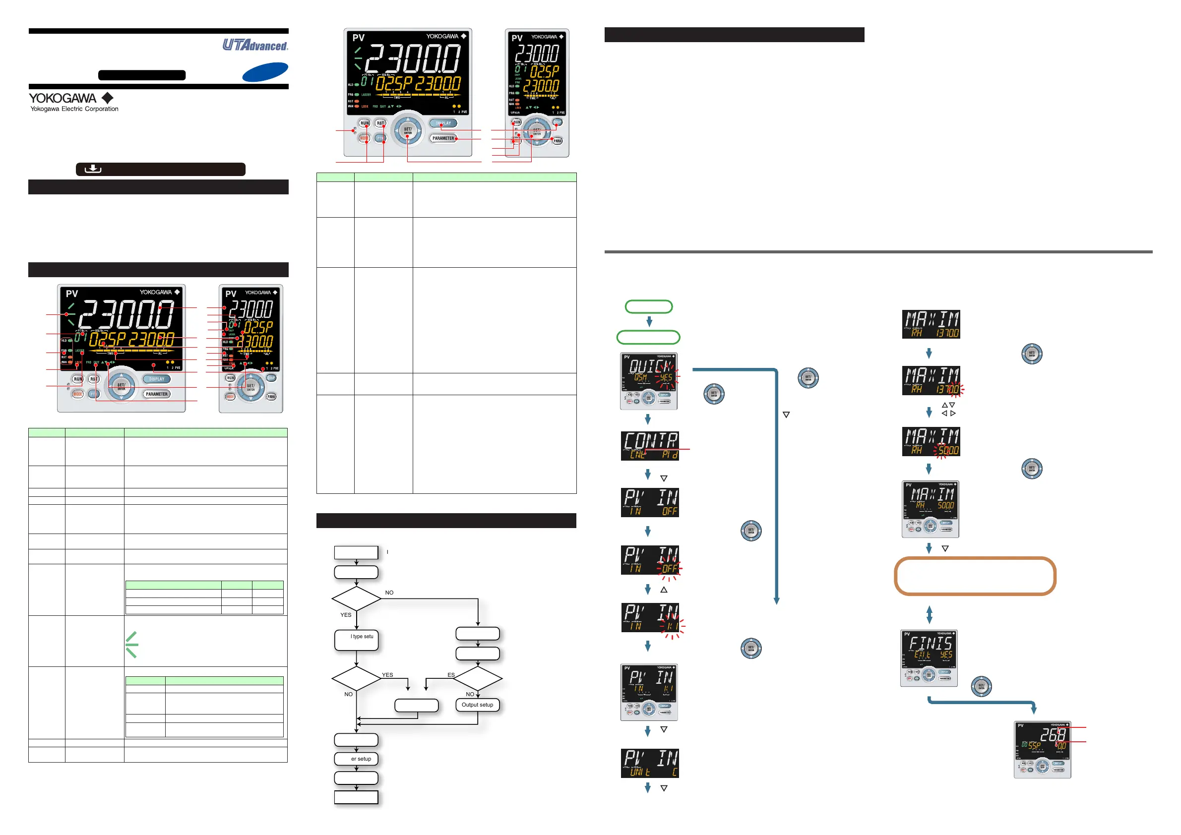
■ FlowofQuickSettingFunction
InQuicksettingmode,theparameterguideappearsonPVdisplay.
Thisguidecanbeturnedon/offwiththeMODEkey.
First, the control type
parameter (CNT) is displayed.
Initial value: PID (PID control)
H/C (Heating/cooling control)
for Heating/cooling type unit.
The PV input type
parameter (IN) is
displayed.
Initial value: OFF
OFF blinks.
Blinking allows you to
change the setting.
K1 is displayed.
K1 has been registered.
The last digit of the upper limit value blinks.
The parameter RH (maximum
value of PV input range) has been
changed to 500.0.
The setpoint for the parameter
RH has been registered.
The PV input unit parameter
(UNIT) is displayed.
Initial value: C (Degree
Celsius)
Press the SET/ENTER key
while YES is displayed to start
the Quick setting.
Select NO with the Down
arrow key and press the
SET/ENTER key.
Select NO to return to
the Operation Display.
Press the Down arrow key.
Press the Down arrow key.
Press the Down arrow key.
Press the Down arrow key.
Press the SET/ENTER key.
Press the SET/ENTER key.
Press the SET/ENTER key.
Press the SET/ENTER key.
Press the Up arrow key.
The upper limit value of the
setting range is displayed for the
parameter RH (maximum value
of PV input range).
Change the setpoint using the Up/Down
arrow keys to increase and decrease the
value and the Left/Right arrow keys to
move between digits.
Finally, EXIT is displayed.
Press the SET/ENTER key to swtich to the setting mode.
Change NO to YES and press the SET/ENTER key to
complete the setup of the basic function.
Operation Display appears.
The Quick setting function continues in the NO state.
Displays the measured
input value (PV).
Displays the starting
target setpoint (SSP).
Follow the same procedure to set RL to 0.0 and
OT to 00.02.
Set other parameters as needed.
Quick setting starts
Power-on
1.
3.
4.
5.
6.
7.
[YES]
[NO]
First, the control type
parameter (CNT) is displayed.
Initial value: PID (PID control)
H/C (Heating/cooling control)
for Heating/cooling type unit.
The PV input type
parameter (IN) is
displayed.
Initial value: OFF
OFF blinks.
Blinking allows you to
change the setting.
K1 is displayed.
K1 has been registered.
The last digit of the upper limit value blinks.
The parameter RH (maximum
value of PV input range) has been
changed to 500.0.
The setpoint for the parameter
RH has been registered.
The PV input unit parameter
(UNIT) is displayed.
Initial value: C (Degree
Celsius)
Press the SET/ENTER key
while YES is displayed to start
the Quick setting.
Select NO with the Down
arrow key and press the
SET/ENTER key.
Select NO to return to
the Operation Display.
Press the Down arrow key.
Press the Down arrow key.
Press the Down arrow key.
Press the Down arrow key.
Press the SET/ENTER key.
Press the SET/ENTER key.
Press the SET/ENTER key.
Press the SET/ENTER key.
The upper limit value of the
setting range is displayed for the
parameter RH (maximum value
of PV input range).
Change the setpoint using the Up/Down
arrow keys to increase and decrease the
value and the Left/Right arrow keys to
move between digits.
Finally, EXIT is displayed.
Press the SET/ENTER key to swtich to the setting mode.
Change NO to YES and press the SET/ENTER key to
complete the setup of the basic function.
Operation Display appears.
The Quick setting function continues in the NO state.
Displays the measured
input value (PV).
Displays the starting
target setpoint (SSP).
Follow the same procedure to set RL to 0.0 and
OT to 00.02.
Set other parameters as needed.
Quick setting starts
Power-on
1.
2.
3.
4.
5.
6.
8.
9.
.
1.
2.
Operation Display

 Loading...


