IM 05P02D41-11EN page 12/14
■ PID Setting Parameter
Menusymbol: (PID)
Parameter
symbol
Name of Parameter Setting Range
Initial
value
User
setting
Display
level
(P)
Proportionalband
Heating-sideproportion-
alband(inHeating/cool-
ingcontrol)
0.0to999.9%
When0.0%isset,itoperatesas0.1%.
Heating-sideON/OFFcontrolapplies
when0.0%inHeating/coolingcontrol
5.0%
EASY
(I)
Integraltime
Heating-sideintegraltime
(inHeating/coolingcontrol)
OFF:Disable
1to6000s
240s
(D)
Derivativetime
Heating-sidederivativetime
(inHeating/coolingcontrol)
OFF:Disable
1to6000s
60s
(OH)
Controloutputhighlimit
Heating-sidecontrol
outputhighlimit(in
Heating/coolingcontrol)
-4.9to105.0%,(OL<OH)
InHeating/coolingcontrol:0.1to
105.0%(OL<OH)
100.0%
(OL)
Controloutputlowlimit
Heating-sidecontrol
outputlowlimit(inHeat-
ing/coolingcontrol)
-5.0to104.9%,(OL<OH),SD:Tight
shut
InHeating/coolingcontrol:0.0to
104.9%(OL<OH)
0.0%
(MR)
Manual reset
EnabledwhenintegraltimeisOFF.
Themanualresetvalueequalsthe
outputvaluewhenPV=SP.
-5.0to105.0%
50.0%
(HYS)
Hysteresis(inON/OFF
control or Position
proportionalcontrol)
Heating-sideON/OFF
controlhysteresis(in
Heating/coolingcontrol)
InON/OFFcontrol:0.0to100.0%of
PVinputrangespan(EUS)
InHeating/coolingcontrolorPosition
proportionalcontrol:0.0to100.0%
In
ON/OFF
control:
0.5%of
PVinput
range
span
In
Heating/
cooling
control or
Position
-
proportional
control:
0.5%
(HY.UP)
Upper-sidehysteresis
(inON/OFFcontrol)
0.0to100.0%ofPVinputrange
span(EUS)
0.5%
ofPV
input
range
span
(HY.LO)
Lower-sidehysteresis
(inON/OFFcontrol)
(DR)
Direct/reverseaction
switch
RVS:Reverseaction
DIR:Directaction
RVS STD
(Pc)
Cooling-sidepropor-
tionalband
0.0to999.9%
(Cooling-sideON/OFFcontrolapplies
when0.0%inHeating/coolingcontrol)
5.0%
EASY
(Ic)
Cooling-sideintegral
time
OFF:Disable
1to6000s
240s
(Dc)
Cooling-sidederivative
time
OFF:Disable
1to6000s
60s
(OHc)
Cooling-sidecontrol
outputhighlimit
0.1to105.0%,(OLc<OHc) 100.0%
(OLc)
Cooling-sidecontrol
output low limit
0.0to104.9%,(OLc<OHc) 0.0%
(HYSc)
Cooling-sideON/OFF
control hysteresis
0.0to100.0% 0.5%
(DB)
Outputdeadband(in
Heating/coolingcontrol
or Position proportional
control)
InHeating/coolingcontrol:-100.0to
50.0%.
InPositionproportionalcontrol:1.0
to10.0%.
3.0%
(PO)
Preset output
Heating-sidepreset
output(inHeating/cool-
ingcontrol)
InRESETmode,xedcontroloutput
canbegenerated.InPositionpropor-
tionalcontrol,Valveopeningcanbe
set;-5.0to105.0%
0.0%
(POc)
Cooling-sidepreset
output
InRESETmode,cooling-sidexed
controloutputcanbegenerated.
-5.0to105.0%
0.0%
IfyouareusingtwoormoregroupsofPIDparameters,usethefollowingtabletorecordtheirsettingvalues.
Parameter n=2 n=3 n=4 R
P
I
D
OH
OL
MR
HYS
HY.UP
HY.LO
DR
Pc
Ic
Dc
OHc
OLc
HYSc
DB
PO
POc
■ Tuning Parameter
Menusymbol:
(TUNE)
Parameter
symbol
Name of Parameter Setting Range
Initial
value
User
setting
Display
level
(SC)
Super function
OFF:Disable
1:Overshootsuppressingfunction
(normalmode)
2:Huntingsuppressingfunction
(stablemode)
Enablestoanswerthewider
characteristicchangescompared
with response mode.
3:Huntingsuppressingfunction
(responsemode)
Enablesquickfollow-upandshort
convergingtimeofPVforthe
changedSP.
4:Overshootsuppressingfunction
(strongsuppressingmode)
Note:Setpoints2and3mustbe
usedinPIDcontrolorPIcontrol.
Disabledinthefollowingcontrols:
1)ON/OFFcontrol,2)PDcontrol,
3)Pcontrol,4)Heating/cooling
control.
Donotusethefunctionforthe
control processes with response
suchasoworpressurecontrol.
OFF EASY
(AT.TY)
Auto-tuningtype
0:Normal
1:Stability
0 STD
(AR)
Anti-resetwindup
(excessintegration
prevention)
AUTO,50.0to200.0% AUTO
STD
(OPR)
Outputvelocitylimiter
OFF:Disable
0.1to100.0%/s
OFF
(MPON)
Manual preset output
numberselection
SelecttheoutputusedinMANmode
whenswitchedfromAUTOtoMAN
mode.
OFF:HoldthecontroloutputinAUTO
mode(bumpless)
1:Usemanualpresetoutput1(outputbump)
2:Usemanualpresetoutput2(outputbump)
3:Usemanualpresetoutput3(outputbump)
4:Usemanualpresetoutput4(outputbump)
5:Usemanualpresetoutput5(outputbump)
OFF
to
(MPO1toMPO5)
Manual preset output 1
to 5
-5.0to105.0%
However,outputislimitedtothe
outputhighlimitandlowlimit.
0.0%
Table
below
Usethefollowingtabletorecordthemanualpresetoutputsettingvalue.
Parameter n=1 n=2 n=3 n=4 n=5
MPOn
■ Zone Control Parameter
Menusymbol: (ZONE)
Parameter
symbol
Name of Parameter Setting Range
Initial
value
User
setting
Display
level
to
(RP1toRP3)
Referencepoint1to3
Set reference points at which switch-
ingiscarriedoutbetweengroupsof
PIDconstantsaccordingtothegiven
temperaturezone.
0.0to100.0%ofPVinputrange(EU)
(RP1≤RP2≤RP3)
100.0%
ofPV
input
range
Table
below
STD
(RHY)
ZonePIDswitching
hysteresis
Hysteresiscanbesetforswitchingat
a reference point.
0.0to10.0%ofPVinputrangespan
(EUS)
0.5%
ofPV
input
range
span
STD
(RDV)
Referencedeviation
SetadeviationfromSP.ThePIDfor
referencedeviationisusedifthere
isalargerdeviationthanthepreset
referencedeviation.
OFF:Disable
0.0+1digitto100.0%ofPVinput
rangespan(EUS)
OFF STD
ForZonecontrol,setthesetupparameterZON(zonePIDselection)toZonePIDselection.
Usethefollowingtabletorecordthereferencepointsettingvalue.
Parameter n=1 n=2 n=3
RPn
■ P Parameter (for Ladder Program)
Menusymbol: (PPAR)
Parameter
symbol
Name of Parameter Setting Range
Initial
value
User
setting
Display
level
to
(P01toP10)
P01toP10parameter
-19999to30000(Setadecimalpoint
positionusingLL50AParameterSet-
tingSoftware.)
0
Table
below
STD
Parameter n=01 n=02 n=03 n=04 n=05 n=06 n=07 n=08 n=09 n=10
Pn
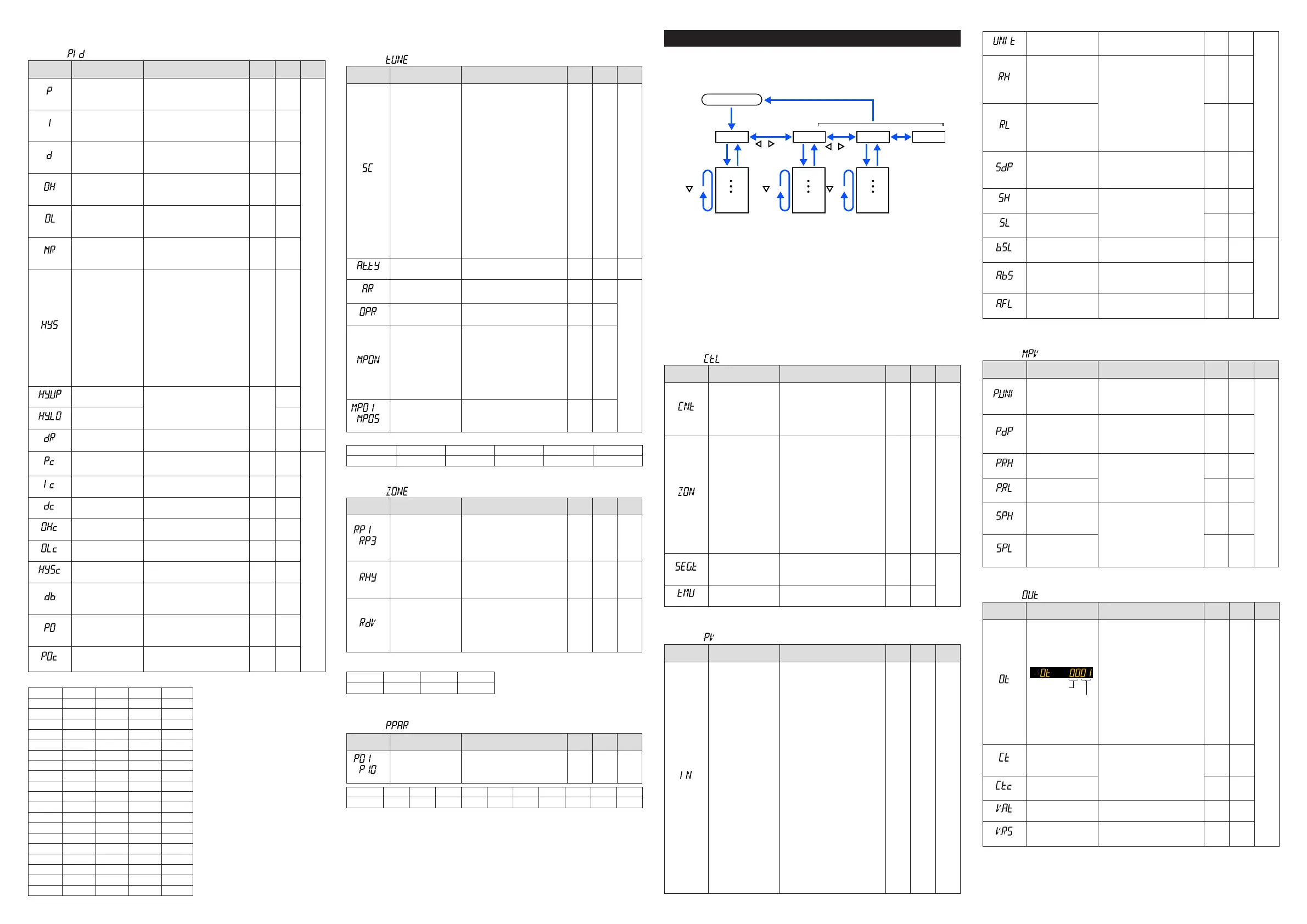
Setup Parameters
HolddownthePARAMETERkeyandLeftarrowkeysimultaneouslyfor3secondsto
movefromtheOperationDisplayorOperationParameterSettingDisplaytotheSetup
ParameterSettingDisplay.
PresstheDISPLAYorDISPkeyoncetoreturntotheOperationDisplay.
Menu
key
key key
key
key
Operation Dsipaly
Parameter
Parameter
Parameter
Parameter
Parameter
Parameter
END
Menu
END
Menu END
END
Menu Display
and Parameter
Setting Display
are changed in a
circular pattern.
Hold down PARAMETER or PARA key and
Left arrow key simultaneously for 3 sec.
DISPLAY or
DISP key
PARAMETER or
PARA key
Move to the Operation Parameter Setting Display: Hold down the PARAMETER or PARA key for 3 sec.
Operation for Setting
· Toselecttheparametersettingdisplayedastheinitialvalue,presstheDownarrow
keytomovetothenextparameter.
· Tochangeandsettheparametersetting,presstheSET/ENTERkeytostarttheset-
pointblinking.Theblinkingstateallowsyoutomakechanges(settingmode).Usethe
Up/Down/Left/Rightarrowkeystochangethesetpoint.PresstheSET/ENTERkeyto
registerthesetting.
NotethattherearesomeparameterswhicharenotdisplayeddependingontheModel
andSuffixcodes,control type(CNT),etc.The parametersforprofessionalsetting
mode(LEVL:PRO)arenotdescribedinthismanual.SeeUser’sManual.
■ Control Function Setting Parameter
Menusymbol: (CTL)
Parameter
symbol
Name of Parameter Setting Range
Initial
value
User
setting
Display
level
(CNT)
Controltype
PID:PIDcontrol
ONOF:ON/OFFcontrol(1pointof
hysteresis)
ONOF2:ON/OFFcontrol(2pointsof
hysteresis)
H/C:Heating/coolingcontrol
PID
or
H/C
(for
Heating/
Cooling-
type)
EASY
(ZON)
ZonePIDselection
0:SegmentPIDselection
1:
ZonePIDselection(selectionbyPV)
2:ZonePIDselection(selectionby
targetSP)
4:
ZonePIDselection(selectionbySP)
5:LocalPIDselection
*Ifsetto“SegmentPIDselection,”
allowsPIDconstantstobeselected
foreachsegments.
*Ifsetto“ZonePIDselection,”
automaticallyselectsPIDconstants
accordingtotherangesetinthe
Referencepoint.
*Ifsetto“LocalPIDselection,”local
PIDisselectedirrespectiveofthe
operation modes.
1 STD
(SEG.T)
Segmentsettingmethod
TIME:Segmenttimesetting
TM.RT:Segmentramp-ratesetting
*Note:Achangeofsettingdeletesa
programpattern.
TIME
EASY
(TMU)
Programtimeunit
HH.MM:hour.minute
MM.SS:minute.second
HH.MM
■ PV Input Setting Parameter
Menusymbol: (PV)
Parameter
symbol
Name of Parameter Setting Range
Initial
value
User
setting
Display
level
(IN)
PVinputtype
OFF:Disable
K1:-270.0to1370.0
0
C/-450.0to2500.0
0
F
K2:-270.0to1000.0
0
C/-450.0to2300.0
0
F
K3:-200.0to500.0
0
C/-200.0to1000.0
0
F
J:-200.0to1200.0
0
C/-300.0to2300.0
0
F
T1:-270.0to400.0
0
C/-450.0to750.0
0
F
T2:0.0to400.0
0
C/-200.0to750.0
0
F
B:0.0to1800.0
0
C/32to3300
0
F
S:0.0to1700.0
0
C/32to3100
0
F
R:0.0to1700.0
0
C/32to3100
0
F
N:-200.0to1300.0
0
C/-300.0to2400.0
0
F
E:-270.0to1000.0
0
C/-450.0to1800.0
0
F
L:-200.0to900.0
0
C/-300.0to1600.0
0
F
U1:-200.0to400.0
0
C/-300.0to750.0
0
F
U2:0.0to400.0
0
C/-200.0to1000.0
0
F
W:0.0to2300.0
0
C/32to4200
0
F
PL2:0.0to1390.0
0
C/32.0to2500.0
0
F
P2040:0.0to1900.0
0
C/32to3400
0
F
WRE:0.0to2000.0
0
C/32to3600
0
F
JPT1:-200.0to500.0
0
C/-300.0to1000.0
0
F
JPT2:-150.0to150.0
0
C/-200.0to300.0
0
F
PT1:-200.0to850.0
0
C/-300.0to1560.0
0
F
PT2:-200.0to500.0
0
C/-300.0to1000.0
0
F
PT3:-150.00to150.00
0
C/-200.0to300.0
0
F
0.4-2V:0.400to2.000V
1-5V:1.000to5.000V
4-20:4.00to20.00mA
0-2V:0.000to2.000V
0-10V:0.00to10.00V
0-20:0.00to20.00mA
-1020:-10.00to20.00mV
0-100:0.0to100.0mV
OFF EASY
(UNIT)
PVinputunit
-:Nounit,C:DegreeCelsius,
-:Nounit,--:Nounit,---:Nounit,
F:DegreeFahrenheit
C
EASY
(RH)
MaximumvalueofPV
inputrange
Dependsontheinputtype.
-Fortemperatureinput-
Setthetemperaturerangethatis
actuallycontrolled.(RL<RH)
-Forvoltage/currentinput-
Settherangeofavoltage/cur-
rentsignalthatisapplied.
Thescaleacrosswhichthevoltage
/currentsignalisactuallycontrolled
shouldbesetusingthemaximum
valueofinputscale(SH)andmini-
mumvalueofinputscale(SL).
(Inputisalways0%whenRL=RH.)
Depends
on the
input type
(RL)
MinimumvalueofPV
inputrange
Depends
on the
input type
(SDP)
PVinputscaledecimal
point position
0:Nodecimalplace
1:Onedecimalplace
2:Twodecimalplaces
3:Threedecimalplaces
4:Fourdecimalplaces
Depends
on the
input type
(SH)
MaximumvalueofPV
input scale
-19999to30000,(SL<SH),
|SH-SL|≤30000
Depends
on the
input type
(SL)
MinimumvalueofPV
input scale
Depends
on the
input type
(BSL)
PVinputburnoutaction
OFF:Disable
UP:Upscale
DOWN:Downscale
Depends
on the
input type
STD
(A.BS)
PVanaloginputbias
-100.0to100.0%ofPVinputrange
span(EUS)
0.0%of
PVinput
range
span
(A.FL)
PVanaloginputlter
OFF,1to120s
OFF
W:W-5%Re/W-26%Re(HoskinsMfg.Co.).ASTME988,WRE:W97Re3-W75Re25
■ Input Range, SP Limiter Setting Parameter
Menusymbol: (MPV)
Parameter
symbol
Name of Parameter Setting Range
Initial
value
User
setting
Display
level
(P.UNI)
ControlPVinputunit
-:Nounit
C:DegreeCelsius
-:Nounit,--:Nounit,---:Nounit
F:DegreeFahrenheit
Same
asPV
input
unit
STD
(P.DP)
ControlPVinputdecimal
point position
0:Nodecimalplace
1:Onedecimalplace
2:Twodecimalplaces
3:Threedecimalplaces
4:Fourdecimalplaces
Depends
on the
input type
(P.RH)
Maximumvalueof
controlPVinputrange
-19999to30000,(P.RL<P.RH),
|P.RH-P.RL|≤30000
Depends
on the
input type
(P.RL)
Minimumvalueofcontrol
PVinputrange
Depends
on the
input type
(SPH)
SPhighlimit
0.0to100.0%ofPVinputrange(EU),
(SPL<SPH)
*Placesthelimitontheprogram
setpoint,orlocalsetpointduring
programoperation.
100.0%
ofPV
input
range
(SPL)
SP low limit
0.0%
ofPV
input
range
■ Output Setting Parameter
Menusymbol: (OUT)
Parameter
symbol
Name of Parameter Setting Range
Initial
value
User
setting
Display
level
(OT)
Outputtypeselection
Upper two
digits
Lower two
digits
ControloutputorHeating-sidecontrol
output(Lowertwodigits)
00:OFF
01:OUTterminals(voltagepulse)
02:OUTterminals(current)
03:OUTterminals(relay)
06:OUT2terminals(relay)
07:RET/OUT2terminals(voltagepulse)
08:RET/OUT2terminals(current)
Cooling-sidecontroloutput(Uppertwodigits)
00:OFF
01:OUTterminals(voltagepulse)
02:OUTterminals(current)
03:OUTterminals(relay)
06:OUT2terminals(relay)
07:RET/OUT2terminals(voltagepulse)
08:RET/OUT2terminals(current)
Standard
type:
00.03
Heating/
cooling
type:
06.03
EASY
(CT)
Controloutputcycletime
Heating-sidecontrol
outputcycletime(in
Heating/coolingcontrol)
0.5to1000.0s
30.0s
(CTc)
Cooling-sidecontrol
output cycle time
30.0s
(V.AT)
Automaticvalveposition
adjustment
OFF:Stopautomaticadjustment
ON:Startautomaticadjustment
OFF
(V.RS)
Valvepositionsetting
reset
SettingV.RStoONresetsthevalve
adjustmentsettingsandcausesthe
indication“V.RS”toblink.
OFF
 Loading...


