IM 05P02D41-11EN page 13/14
(V.L)
Fully-closedvalveposi-
tionsetting
PressingtheSET/ENTERkeywithvalve
positionsettothefully-closedposition
byDownarrowkeycausestheadjusted
valuetobestored.WhenV.Ladjustment
iscompleted,V.Lstopsblinking.
-
EASY
(V.H)
Fully-openedvalve
positionsetting
PressingtheSET/ENTERkeywithvalve
positionsettothefully-openedposition
byUparrowkeycausestheadjusted
valuetobestored.WhenV.Hadjust
-
ment
iscompleted,V.Hstopsblinking.
-
(TR.T)
Valvetravelingtime 5to300s 60s
STD
(V.MOD)
Valveadjustingmode
0:Valvepositionfeedbacktype
1:
Valvepositionfeedbacktype(moves
totheestimatingtypeifafeedback
inputerrororbreakoccurs.)
2:Valvepositionestimatingtype
0
(RTS)
Retransmissionoutput
typeofRET
OFF:Disable
PV1:PV
SP1:SP
OUT1:
OUT(Valveopening:0to100%
inPositionproportionalcontrol)
LPS:15VDClooppowersupply
TSP1:TargetSP
HOUT1:Heating-sideOUT
COUT1:Cooling-sideOUT
MV1:Positionproportionaloutput
(internalcomputedvalue)
PV:PVterminalsanaloginput
PV1 EASY
(RTH)
Maximumvalueof
retransmission output
scaleofRET
WhenRTS=PV1,SP1,TSP1,PV
RTL+1digitto30000
-19999toRTH-1digit
Decimalpointposition:
WhenRTS=PV1,SP1,orTSP1,
decimal point position is same as
thatofPVinput.
WhenRTS=PV,decimalpointposition
issameasthatofPVinputscale.
100%
ofPV
input
range
STD
(RTL)
Minimumvalueof
retransmission output
scaleofRET
0%
ofPV
input
range
(O1RS)
Retransmissionoutput
typeofOUTcurrent
output
SameasRTS
OFF
STD
(O1RH)
Maximumvalueof
retransmission output
scaleofOUTcurrent
output
WhenO1RS=PV1,SP1,TSP1,PV
O1RL+1digitto30000
-19999toO1RH-1digit
Decimalpointposition:
WhenO1RS=PV1,SP1,orTSP1,deci
-
mal point position is same as that of
PV
input.
WhenO1RS=PV,decimalpointposition
issameasthatofPVinputscale.
-
(O1RL)
Minimumvalueof
retransmission output
scaleofOUTcurrent
output
-
(OU.A)
OUTcurrentoutput
range
4-20:4to20mA
0-20:0to20mA
20-4:20to4mA
20-0:20to0mA
4-20
STD
(RET.A)
RETcurrentoutput
range
4-20
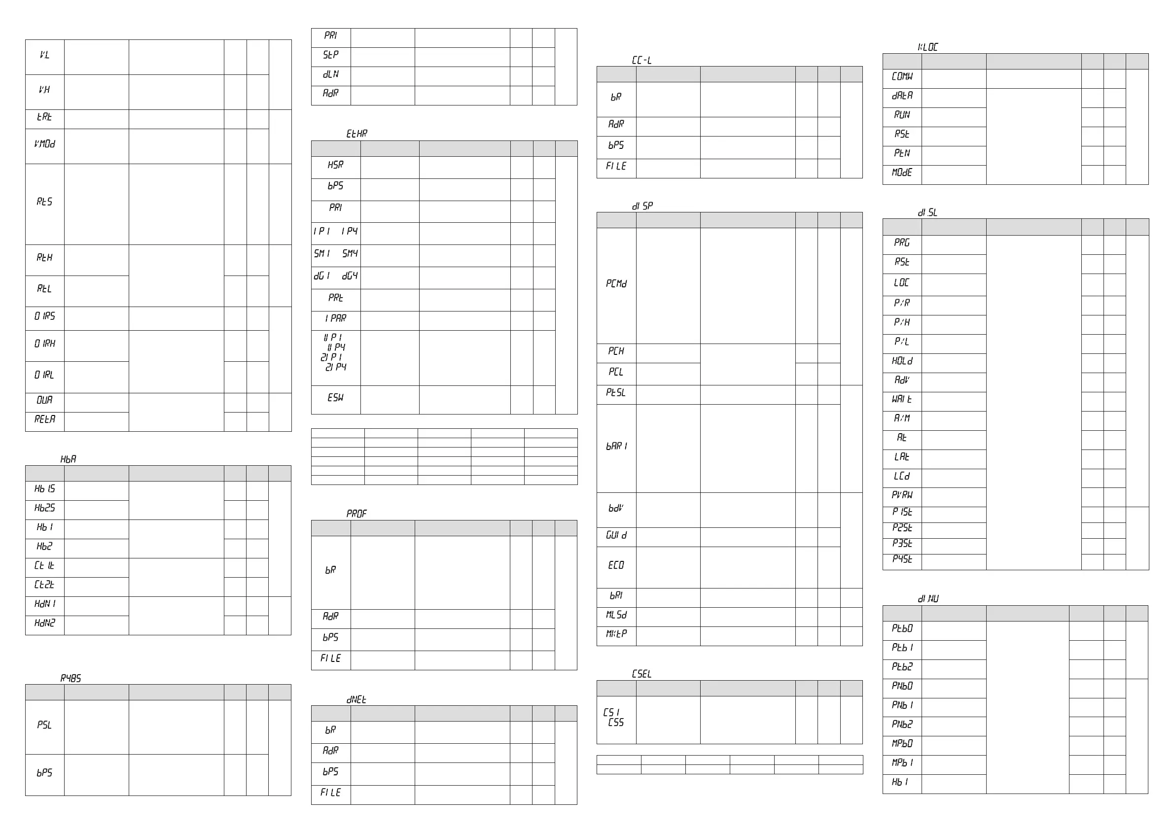
■ Heater Break Alarm Setting Parameter
Menusymbol: (HBA)
Parameter
symbol
Name of Parameter Setting Range
Initial
value
User
setting
Display
level
(HB1.S)
Heaterbreakalarm-1
function selection
0:Heatercurrentmeasurement
1:Heaterbreakalarm
1
EASY
(HB2.S)
Heaterbreakalarm-2
function selection
1
(HB1)
Heaterbreakalarm-1
current setpoint
OFF,0.1to300.0Arms
OFF
(HB2)
Heaterbreakalarm-2
current setpoint
OFF
(CT1.T)
CT1
coilwindingnumberratio
1to3300
800
(CT2.T)
CT2
coilwindingnumberratio
800
(HDN1)
Heaterbreakalarm-1
On-delaytimer
0.00to99.59(m.s)
0.00
STD
(HDN2)
Heaterbreakalarm-2
On-delaytimer
0.00
IncaseswherethecurrenttransformersmanufacturedbyU.R.D.Co.,Ltdareused,setthefollowingvaluefor
thecoilwindingnumberratio.CTL-6-S-H:800,CTL-12L-30:3000
■
RS-485 Communication Setting Parameter (E3-terminal Area)
Menusymbol: (R485)
Parameter
symbol
Name of Parameter Setting Range
Initial
value
User
setting
Display
level
(PSL)
Protocol selection
PCL:PClinkcommunication
PCLSM:PClinkcommunication(with
checksum)
LADR:Laddercommunication
CO-M:Coordinatedmasterstation
MBASC:Modbus(ASCII)
MBRTU:Modbus(RTU)
P-P:Peer-to-peercommunication
MBRTU
EASY
(BPS)
Baud rate
600:600bps,1200:1200bps,
2400:2400bps,4800:4800bps,
9600:9600bps,19200:19.2kbps,
38400:38.4kbps
*ThebaudrateforRS-485isupto
19.2kbpsinE4-terminalarea.
19200
(PRI)
Parity
NONE:None,EVEN:Even,
ODD:Odd
EVEN
(STP)
Stopbit 1:1bit,2:2bits 1
(DLN)
Datalength 7:7bits,8:8bits 8
(ADR)
Address 1to99 1
■
Ethernet Communication Setting Parameter (E3-terminal Area)
Menusymbol: (ETHR)
Parameter
symbol
Name of Parameter Setting Range
Initial
value
User
setting
Display
level
(HSR)
High-speedresponse
mode
OFF,1to8 1
EASY
(BPS)
Baud rate
9600:9600bps,19200:19.2kbps,
38400:38.4kbps
38400
(PRI)
Parity
NONE:None,EVEN:Even,
ODD:Odd
EVEN
to
(IP1toIP4)
IP address 1 to 4
0to255
Initialvalue:(IP1).(IP2).(IP3).(IP4)=
(192).(168).(1).(1)
See left
Table
below
to
(SM1toSM4)
Subnetmask1to4
0to255
Initialvalue:(SM1).(SM2).(SM3).
(SM4)=(255).(255).(255).(0)
See left
Table
below
to
(DG1toDG4)
Defaultgateway1to4
0to255
Initialvalue:(DG1).(DG2).(DG3).
(DG4)=(0).(0).(0).(0)
See left
Table
below
(PRT)
Portnumber 502,1024to65535 502
(IPAR)
IP access restriction OFF:Disable,ON:Enable OFF
to
,
to
(1.IP1to1.IP4,
2.IP1to2.IP4)
Permitted IP address
1-1to1-4
Permitted IP address
2-1to2-4
0to255
Initialvalue:
(1.IP1).(1.IP2).(1.IP3).(1.IP4)=
(255).(255).(255).(255)
(2.IP1).(2.IP2).(2.IP3).(2.IP4)=
(255).(255).(255).(255)
See left
Table
below
(ESW)
Ethernetsettingswitch
Settingthisparameterto“ON”en-
ablestheEthernetcommunication
parametersettings.
OFF,ON
OFF
UsethefollowingtabletorecordEthernetcommunicationsettingvalue.
Parameter n=1 n=2 n=3 n=4
IPn
SMn
DGn
1.IPn
2.IPn
■
PROFIBUS-DP Communication Setting Parameter (E3-terminal Area)
Menusymbol: (PROF)
Parameter
symbol
Name of Parameter Setting Range
Initial
value
User
setting
Display
level
(BR)
Baud rate
9.6K:9.6kbps
19.2K:19.2kbps
93.75K:93.75kbps
187.5K:187.5kbps
0.5M:0.5Mbps
1.5M:1.5Mbps
3M:3Mbps
6M:6Mbps
12M:12Mbps
AUTO
45.45K:45.45kbps
AUTO
EASY
(ADR)
Address 0to125 3
(BPS)
Baud rate
9600:9600bps
19200:19.2kbps
38400:38.4kbps
38400
(FILE)
Prolenumber 0,11to13 0
■
DeviceNet Communication Setting Parameter (E3-terminal Area)
Menusymbol: (DNET)
Parameter
symbol
Name of Parameter Setting Range
Initial
value
User
setting
Display
level
(BR)
Baud rate
125K:125kbps
250K:250kbps
500K:500kbps
125M
EASY
(ADR)
Address 0to63 63
(BPS)
Baud rate
9600:9600bps
19200:19.2kbps
38400:38.4kbps
38400
(FILE)
Prolenumber 0,11to13 0
■
CC-Link Communication Setting Parameter (UP35A: E3-terminal
Area, UP32A: E1-terminal Area)
Menusymbol: (CC-L)
Parameter
symbol
Name of Parameter Setting Range
Initial
value
User
setting
Display
level
(BR)
Baud rate
156K:156kbps
625K:625kbps
2.5K:2.5kbps
5M:5Mbps
10M:10Mbps
10M
EASY
(ADR)
Address 1 to 64 3
(BPS)
Baud rate
9600:9600bps
19200:19.2kbps
38400:38.4kbps
38400
(FILE)
Prolenumber
0,11to13
(0,11:Ver.1.10)(12,13:Ver.2.00)
0
■DisplayFunctionSettingParameter
Menusymbol: (DISP)
Parameter
symbol
Name of Parameter Setting Range
Initial
value
User
setting
Display
level
(PCMD)
ActivecolorPVdisplay
switch
0:Fixedinwhite
1:Fixedinred
2:Linktoalarm1(AlarmOFF:white,
AlarmON:red)
3:Linktoalarm1(AlarmOFF:red,
AlarmON:white)
4:Linktoalarm1or2(AlarmOFF:
white,AlarmON:red)
5:Linktoalarm1or2(AlarmOFF:
red,AlarmON:white)
6:PVlimit(Withinrange:white,Out
ofrange:red)
7:PVlimit(Withinrange:red,Outof
range:white)
8:SPdeviation(Withindeviation:
white,Outofdeviation:red)
9:SPdeviation(Withindeviation:red,
Outofdeviation:white)
10:LinktoDI(ON:red,OFF:white)
0
EASY
(PCH)
PVcolorchangehigh
limit
SetadisplayvaluewheninPVlimit
orSPdeviation.
-19999to30000(Setavaluewithin
theinputrange.)
Decimalpointpositiondependson
the input type.
0
(PCL)
PVcolorchangelowlimit 0
(PTSL)
Programdisplaypattern
selection
PTN:Patterndisplay
SK.RP:Rampandsoakdisplay
PTN
STD
(BAR1)
Bar-graphdisplayregis-
tration
0:Disable
1:
OUT,Heating-sideOUT,Internalvalue
in Position proportional control
2:Cooling-sideOUT
3:PV
4:SP
5:Deviation
6to16:Disable
17:Feedbackinput(valveopening)
18:PVterminalsanaloginput
19to22:Disable
23:Timeeventandalarmstatus
24:TSP
25:TSPdeviation
23
(BDV)
Bar-graphdeviation
displayband
0.0to100.0%ofPVinputrangespan
(EUS)
1.0%
ofPV
input
range
span
STD
(GUID)
GuidedisplayON/OFF OFF:Nondisplay,ON:Display ON
(ECO)
Economymode
OFF:Disable
1:EconomymodeON(Allindications
exceptPVdisplayOFF)
2:EconomymodeON(Allindications
OFF)
3:Brightness10%(wholeindication)
OFF
(BRI)
Brightness (Dark)1to5(Bright) 3 EASY
(MLSD)
Leastsignicantdigital
maskofPVdisplay
OFF:Withleastsignicantdigit
ON:Withoutleastsignicantdigit
OFF STD
(MKTP)
Methodforleastsignicant
digitalmaskofPVdisplay
0:Rounding,1:Rounding-off 0 STD
■SELECTDisplaySettingParameter
Menusymbol: (CSEL)
Parameter
symbol
Name of Parameter Setting Range
Initial
value
User
setting
Display
level
to
(CS1toCS5)
SELECTDisplay-1to-5
registration
Registertheoperationparameter
(excepttheOperationMode)thatis
frequentlymodiedtodisplayitinthe
OperationDisplay.
OFF,2201to5000,6701to6710
Forthesettingrange,seeCommuni-
cationUser'sManual.
OFF STD
UsethefollowingtabletorecordSELECTDisplaysettingvalue.
Parameter n=1 n=2 n=3 n=4 n=5
CSn
■KeyLockSettingParameter
Menusymbol: (KLOC)
Parameter
symbol
Name of Parameter Setting Range
Initial
value
User
setting
Display
level
(COM.W)
Communicationwrite
enable/disable
OFF:Enable,ON:Disable OFF
STD
(DATA)
Front panel parameter
data(▼,▲)keylock
OFF:Unlock,ON:Lock
OFF
(RUN)
FrontpanelRUNkey
lock
OFF
(RST)
FrontpanelRSTkeylock OFF
(PTN)
FrontpanelPTNkeylock OFF
(MODE)
FrontpanelMODEkey
lock
OFF
■DIFunctionRegistrationParameter
Menusymbol: (DI.SL)
Parameter
symbol
Name of Parameter Setting Range
Initial
value
User
setting
Display
level
(PRG)
SwitchtoPROG(Start
ofprogramoperation)
SetanIrelaynumberofcontact
input.
Set“OFF”todisablethefunction.
Standard terminals
DI1:5025,DI2:5026,DI3:5027
E4-terminalarea
DI41:5089,DI42:5090,DI43:5091,
DI44:5092,DI45:5093
5025
STD
(RST)
SwitchtoRESET(Stop
ofprogramoperation)
5026
(LOC)
SwitchtoLOCAL(LSP)
(Startoflocal-mode
operation)
5027
(P/R)
PROG/RESETSwitch OFF
(P/H)
PROG/HOLDSwitch OFF
(P/L)
PROG/LOCAL(LSP)
Switch
OFF
(HOLD)
SwitchtoHOLD(Start
ofhold-modeoperation)
OFF
(ADV)
Advanceofsegment OFF
(WAIT)
WaitON/OFFswitch OFF
(A/M)
AUTO/MANswitch OFF
(AT)
Auto-tuningSTART/STOP
switch
OFF
(LAT)
Latchrelease OFF
(LCD)
LCDbacklightON/OFF
switch
OFF
(PVRW)
PVred/whiteswitch
OFF
(P1ST)
Prog/resetswitchof
programpattern-1
OFF
STD
(P2ST)
Prog/resetswitchof
programpattern-2
OFF
(P3ST)
Prog/resetswitchof
programpattern-3
OFF
(P4ST)
Prog/resetswitchof
programpattern-4
OFF
■DIFunctionNumberingParameter
Menusymbol: (DI.NU)
Parameter
symbol
Name of Parameter Setting Range Initial value
User
setting
Display
level
(PT.B0)
Bit-0ofprogrampattern
number
SetanIrelaynumberofcontact
input.
Set“OFF”todisablethefunc-
tion.
Standard terminals
DI1:5025,DI2:5026,DI3:5027
E4-terminalarea
DI41:5089,DI42:5090,DI43:
5091,DI44:5092,DI45:5093
UP35A:5089
UP32A:OFF
EASY
(PT.B1)
Bit-1ofprogrampattern
number
UP35A:5090
UP32A:OFF
(PT.B2)
Bit-2ofprogrampattern
number
UP35A:5091
UP32A:OFF
(PN.B0)
Bit-0ofPIDnumber OFF
STD
(PN.B1)
Bit-1ofPIDnumber OFF
(PN.B2)
Bit-2ofPIDnumber OFF
(MP.B0)
Bit-0ofmanualpreset
outputnumber
OFF
(MP.B1)
Bit-1ofmanualpreset
outputnumber
OFF
(MP.B2)
Bit-2ofmanualpreset
outputnumber
OFF
■ Output Setting Parameter (Continued)
SetupParameters(Continuedfrompage12)
 Loading...


