IM 05P02D41-11EN page 14/14
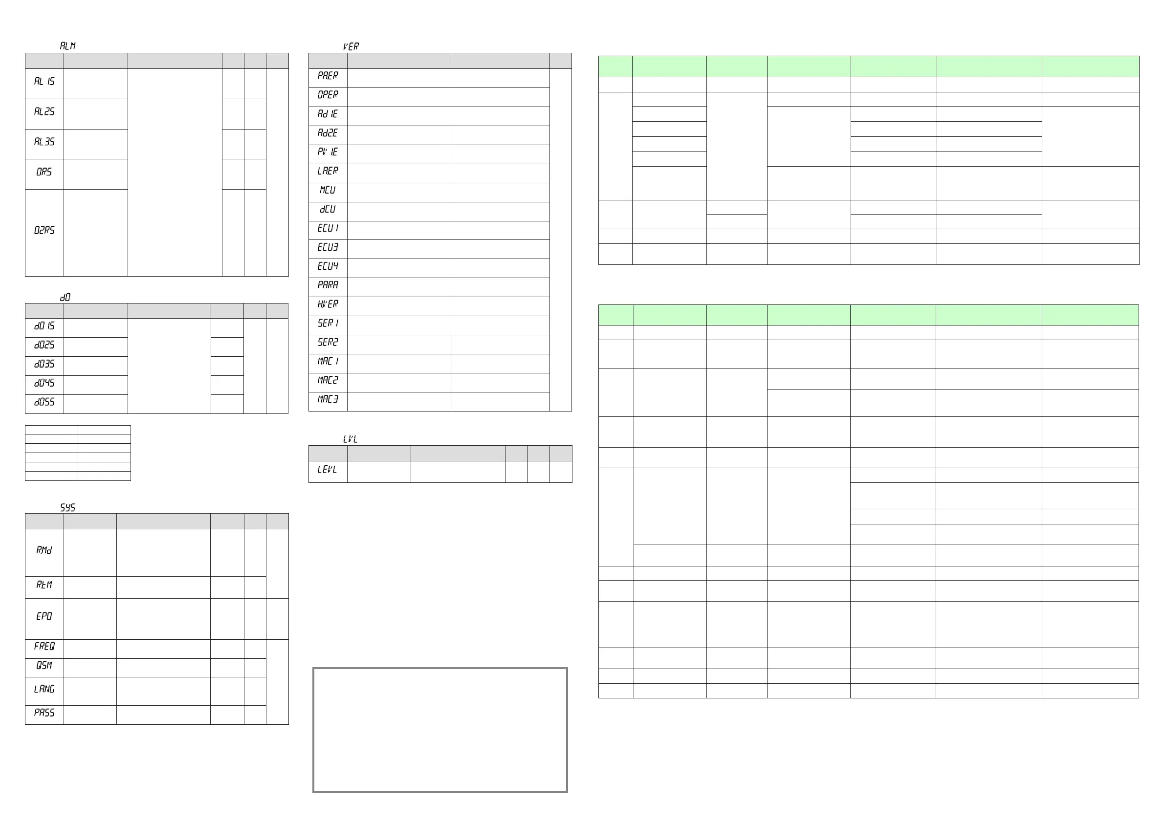
■AL1-AL3FunctionRegistrationParameter
Menusymbol: (ALM)
Parameter
symbol
Name of Parameter Setting Range
Initial
value
User
setting
Display
level
(AL1.S)
AL1functionselection
SetanIrelaynumber.
Fortheitemsotherthanbelow,see
CommunicationUser'sManual.
Ex.)Setthenumber4353forAL1.S
to use the alarm 1.
Set“OFF”todisablethefunction.
Settingrange:4001to6304
Nofunction:OFF
PVevent1:4801,
PVevent2:4802
Timeevent1:4817,
Timeevent2:4818,
Timeevent3:4819,
Timeevent4:4821
Alarm1:4353
Alarm2:4354
AUTO(OFF)/MAN(ON)status:
4177
ProgramRESETstatus:4181
ProgramRUNstatus:4182
Localoperationstatus:4183
HOLDmodestatus:4189
Programadvancestatus:4187
Patternendsignal(1second):4265
Patternendsignal(3seconds):4266
Patternendsignal(5seconds):4267
Waitendsignal(1second):4257
Waitendsignal(3seconds):4258
Waitendsignal(5seconds):4259
FAIL(NormallyON)output:4256
4801
STD
(AL2.S)
AL2functionselection 4802
(AL3.S)
AL3functionselection 4817
(OR.S)
OUTrelayfunction
selection
OFF
(OR2.S)
OUT2relayfunction
selection
OFF
■DOSettingParameter(E1-terminalArea)
Menusymbol: (DO)
Parameter
symbol
Name of Parameter Setting Range Initial value
User
setting
Display
level
(DO1.S)
DO11functionselection
SameasAL1.S
Set“OFF”todisablethefunction.
UP35A:4353
UP32A:OFF
Table
below
STD
(DO2.S)
DO12functionselection
UP35A:4354
UP32A:OFF
(DO3.S)
DO13functionselection
UP35A:4818
(DO4.S)
DO14functionselection
UP35A:4819
(DO5.S)
DO15functionselection
UP35A:4821
UsethefollowingtabletorecordDOsettingvalue.
Parameter E1-terminalArea
DO1.S
DO2.S
DO3.S
DO4.S
DO5.S
■SystemSettingParameter
Menusymbol: (SYS)
Parameter
symbol
Name of Parameter Setting Range Initial value
User
setting
Display
level
(R.MD)
Restartmode
Sethowthecontrollershouldrecoverfrom
a power failure of 5 seconds or more.
CONT:Continueactionsetbefore
power failure.
MAN:StartfromMAN.
RESET:StartfromAUTOandRESET.
Outputsthepresetoutputvalue.
CONT
STD
(R.TM)
Restarttimer
Settimebetweenpoweronandthe
instant where controller starts compu-
tation.0to10s
0
(EPO)
Input error preset
output
Setpresetoutputvaluewhentheinputburnout
orADCerroroccurs.Manualoutputispriori-
tized
whentheinputburnoutoccursinMAN.
0:Presetoutput
1:0%output
2:100%output
0 STD
(FREQ)
Powerfrequency AUTO,60:60Hz,50:50Hz AUTO
EASY
(QSM)
Quicksettingmode
OFF:Disable
ON:Enable
ON
(LANG)
Guidedisplay
language
ENG:English
FRA:French
GER:German
SPA:Spanish
Dependson
the model
andsufx
codes
(PASS)
Passwordsetting 0(Nopassword)to65535 0
■
ErrorandVersionConrmationParameter(fordisplayonly)
Menusymbol: (VER)
Parameter
symbol
Name of Parameter Status record
Display
level
(PA.ER)
Parameter error status
EASY
(OP.ER)
Optionerrorstatus
(AD1.E)
A/Dconvertererrorstatus1
(AD2.E)
A/Dconvertererrorstatus2
(PV1.E)
PVinputerrorstatus
(LA.ER)
Laddererrorstatus
(MCU)
MCUversion
(DCU)
DCUversion
(ECU1)
ECU-1version(E1-terminalarea)
(ECU3)
ECU-3version(E3-terminalarea)
(ECU4)
ECU-4version(E4-terminalarea)
(PARA)
Parameterversion
(H.VER)
Productversion
(SER1)
Serialnumber1
(SER2)
Serialnumber2
(MAC1)
MACaddress1(E3-terminalarea)
(MAC2)
MACaddress2(E3-terminalarea)
(MAC3)
MACaddress3(E3-terminalarea)
■ParameterDisplayLevelParameter
Menusymbol: (LVL)
Parameter
symbol
Name of Parameter Setting Range
Initial
value
User
setting
Display
level
(LEVL)
Parameterdisplaylevel
EASY:Easysettingmode
STD:Standardsettingmode
PRO:Professionalsettingmode
STD EASY
*ForProfessionalsettingmode,seeUser’sManual.
Trademarks
● Our product names or brand names mentioned in this manual are
the trademarks or registered trademarks of Yokogawa Electric Corporation.
● Adobe, Acrobat, and Postscript are either registered trademarks or trademarks
of Adobe Systems Incorporated.
● Ethernet is a registered trademark of XEROX Corporation in the United States.
● Modbus is a registered trademark of Schneider Electric.
● PROFIBUS-DP is a registered trademark of PROFIBUS User Organization.
● DeviceNet is a registered trademark of Open DeviceNet Vendor Association.
● CC-Link is a registered trademark of CC-Link Partner Association.
● We do not use the TM or ® mark to indicate these trademarks or
registered trademarks in this manual.
● All other product names mentioned in this manual are trademarks
or registered trademarks of their respective companies.
[ Operations 13. Troubleshooting ] ■ Errors at Power On
Theerrorsshownbelowmayoccurinthefaultdiagnosiswhenthepoweristurnedon.(FordetailsofSetpointdisplayandinput/outputactionwheneacherroroccurs,seeUser’sManual.
PV display
(Operation
Display)
Setpoint display
(Operation Display)
Status indicator
(Operation Display)
Parameter that displays error
details
Error description Cause and diagnosis Remedy
Indication off Indication off — — FaultyMCURAM/MCUROM MCURAM/MCUROMarefailed.
Faulty.
Contactusforrepair.
ERR
SYS-----
—
— System data error System data is corrupted.
Faulty.
Contactusforrepair.
PAR0004
(foruserdefaultvalueerroronly)
Setupparameter(PA.ER)
User(parameter)defaultvalue
error
Userparameteriscorrupted.
Initializedtofactorydefaultvalue.
Checkandreconguretheinitialized
settingparameters.Errorindicationis
erased when the power is turned on
again.
PAR0010
(forsetupparametererroronly)
Setup parameter error
Setup parameter data is corrupted.
Initializedtouserdefaultvalue.
PAR0020
(foroperationparametererroronly)
Operationparametererror
Operationparameterdataiscorrupted.
Initializedtouserdefaultvalue.
PAR0040
(forprogrampatternerroronly)
Programpatternerror
Programpatterndataiscorrupted.
Allprogrampatternsaredeleted.
SLOT0015
(0015:Erroroccurstoall
hardwareofE1toE4-terminal
areas.)
Setupparameter(OP.ER)
Nonrespondinghardwareof
extendedfunction(E1toE4-
terminalareas)
Inconsistence of system data and
hardwareofextendedfunction.
Nonrespondingcommunicationbetween
hardwareofextendedfunction(E1toE4-
terminalareas).
Faulty.
Contactusforrepair.
Normal
indication
Normalindication
Rightmostdecimalpoint
onPVdisplayblinks.
Setupparameter(PA.ER)
Calibrationvalueerror
Initializedtocalibrateddefaultvaluebecause
ofcorruptedfactorydefaultvalue.
Faulty.
Contactusforrepair.
Rightmostdecimalpoint
onSymboldisplayblinks.
FaultyFRAM
Datawriting(storing)toFRAMisimpossible.
Normal
indication
Normalindication LADDERlampblinks Setupparameter(LA.ER) Corruptedladderprogram
Ladderprogramiscorrupted.
Operateswithoutladderprogram.
Downloadtheladderprogramagain.
Normal
indication
0.00000000
(Decimalpointontheleftof
theSymboldisplayblinks)
— Setupparameter(OP.ER) Userproleerror Userproleiscorrupted. Downloadtheuserproleagain.
[ Operations 13. Troubleshooting ] ■ Errors during Operation
Theerrorsshownbelowmayoccurduringoperation.(Forinput/outputactionwheneacherroroccurs,seeUser’sManual.
PV display
(Operation
Display)
Setpoint display
(Operation Display)
Status indicator
(Operation Display)
Parameter that displays
error details
Error description Cause and diagnosis Remedy
AD.ERR
Normalindication(Note) — Setupparameter(AD1.E)
AnaloginputterminalADCerror
•PVinput
AnaloginputterminalADvalueerror
Faulty.
Contactusforrepair.
RJC.E
(DisplaysRJC.
EandPV
alternately.)
Normalindication(Note) — Setupparameter(AD1.E)
UniversalinputterminalRJCerror
•PVinput
UniversalinputterminalRJCerror
Faulty.
Contactusforrepair.
SettheparameterRJCtoOFFtoerase
error indication.
B.OUT
Normalindication(Note) —
Setupparameter(AD1.E)
Analoginputterminalburnouterror
•PVinput
Analoginputterminalsensorburnout
Checkwiringandsensor.
Errorindicationiserasedinnormal
operation.
Setupparameter(PV1.E) PVinputburnouterror BurnoutofanaloginputconnectedtoPV
Checkwiringandsensorofconnected
analoginputterminals.
Errorindicationiserasedinnormal
operation.
OVER
-OVER
Normalindication — Setupparameter(PV1.E)
PVinputover-scale
PVinputunder-scale
(PVvaluesoutof-5to105%)
PVinputisoutof-5to105%.Alsooccurs
whenthedataoutofrangewhichisthe
ladder calculation result is input.
Checkanaloginputvalueorladder
program.
Normal
indication
OUT-----
— Setupparameter(AD2.E)
Feedbackinputresistor/current
burnout
Feedbackinputburnout
Checkwiringoffeedbackinputresistor/
current.Errorindicationiserasedin
normal operation.
Normal
indication
Normalindication LADDERlampblinks Setupparameter(LA.ER)
Laddercalculationoverow
Floatingpointcomputationforladder
calculationisinnite.
Checktheladderprogram.
Loadfactorover100%
Computationdoesnotendwithinthe
controlperiod.(Whentheloadfactoris
100%ormore,andthecomputationdoes
notendwithinthecontrolperiod.)
Changethecontrolperiodorreduce
thenumberofstepsfortheladder
program.
Loadfactorover200%
(Forcedend)
Computationdoesnotendwithinthecontrol
period(loadfactoris200%ormore).
Changethecontrolperiodorreducethe
numberofstepsfortheladderprogram.
Ladderprogramerror Ladderprogramiscorrupted.
Downloadtheladderprogramagain.If
the error indication is still not erased,
thereisafault.Contactusforrepair.
0.00000000
(Decimalpointontheleftof
theSymboldisplayblinks)
— Setupparameter(OP.ER) Peer-to-peercommunicationerror Peer-to-peercommunicationerror
Checkthatthetargetdevicesare
connected correctly.
Recoveryatnormalreceipt.
AT.E
Normalindication — Setupparameter(PV1.E) Auto-tuningtime-out
Auto-tuningdoesnotendevenwhen24
hourshaveelapsedafterthestartoftuning.
Checktheprocess.Holddownanykeyto
erase the error indication
VAT.E
Normalindication — Setupparameter(AD2.E)
Valvepositionautomatic
adjustmenterror
Fully-closedvalvepositionisequaltoorlarger
thanthefully-openvalvepositionafterautomatic
valvepositionadjustmentisperformed.
Checkwiringandvalve.Holddownany
key to erase the error indication.
Normal
indication
0.00000000
(Decimalpointontheleftof
theSymboldisplayblinks)
— Setupparameter(OP.ER)
Communicationerror
(RS-485communication)
Framingparityerror
Bufferoverow
Inter-charactertime-out
Checksumerror(PClinkcommunicationwith
checksum)
CRCcheckerror(Modbus/RTU)
LRCcheckerror(Modbus/ASCII)
Checkthecommunicationparameters.
Recoveryatnormalreceipt.
Holddownanykeytostopblinking.
Normal
indication
0.00000000
(Decimalpointontheleftof
theSymboldisplayblinks)
— Setupparameter(OP.ER) Userproleerror Userproleiscorrupted. Downloadtheuserproleagain.
Normal
indication
Normalindication
Rightmostdecimalpointon
Symboldisplayblinks.
Setupparameter(PA.ER) FaultyFRAM
Writing(storing)datatoFRAMisimpossible.
Faulty.Contactusforrepair.
Undened Undened — —
FaultyMCU/DCU
(ROM/RAMerror,corrupted)
MCU/DCUiscorrupted. Faulty.Contactusforrepair.
Note:WhenanerroroccursininputshowninAnaloginputdisplay(Operationdisplay),SetpointdisplayshowsthesamesymbolasthePVdisplay.
 Loading...


