JOHNSON CONTROLS
25
SECTION 2 – OPTIVIEW CONTROL CENTER
FORM 160.79-O3
ISSUE DATE: 11/09/2018
2
OPTIVIEW CONTROL CENTER IN DETAIL
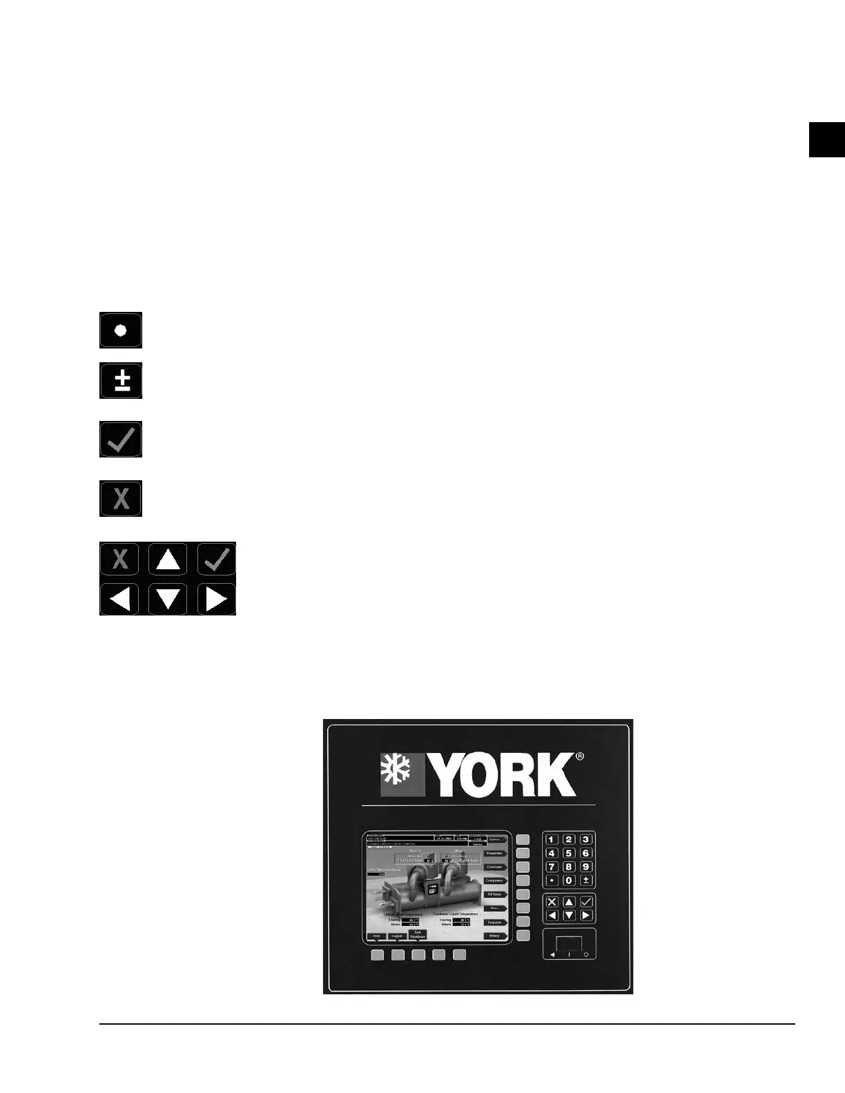
The OptiView™ Control Center display is highlighted
by a full screen graphics display. This display is nested
within a standard keypad, and is surrounded by “soft”
keys which are redefined based on the currently dis-
played screen. Eight buttons are available on the right
side of the panel, and are primarily used for navigation
between the system screens. At the base of the display
are 5 additional buttons. The area to the right of the
keypad is used for data entry with a standard numeric
keypad provided for entry of system setpoints and lim-
its.
The Decimal key provides accurate entry of
setpoint values.
A +/- key has also been provided to allow entry
of negative values and AM/PM selection dur-
ing time entry.
In order to accept changes made to the chiller
setpoints, the Check key is provided as a uni-
versal ‘Enter’ key or ‘Accept’’ symbol.
In order to reject entry of a setpoint or dismiss
an entry form, the ‘X’ key is provided as a uni-
versal ‘Cancel’ symbol.
Cursor Arrow keys are pro-
vided to allow movement on
screens which contain a large
amount of entry data. In ad-
dition, these keys can be used
to scroll through history and
event logs.
The Start/Stop control is operated via a three-position
rocker switch. When toggled all the way to the right, it
is considered in the STOP/RESET position. When in
the middle position, this is considered the RUN state.
When toggled to the left-most position, it is considered
in the START state. Each state is described in detail
below:
• STOP / RESET (O)
When in this position, the chiller will not run un-
der any condition. The switch must be placed in
this state following a Safety shutdown before the
chiller is allowed to restart. This guarantees that
manual intervention has taken place and the shut-
down has been acknowledged.
• START ()
The switch can only remain in this position when
being acted upon by a manual force. Once the user
has released the switch, it automatically reverts to
the RUN position. Generally, this state only oc-
curs momentarily as the operator attempts to lo-
cally start the unit. Once this position has been
sensed, if all fault conditions are cleared, the unit
will enter the system prelube (start sequence).
• RUN ()
When in this position, the chiller is able to oper-
ate. The switch spring-returns to this state after it
has been toggled to the START position. When
in this state, the chiller is allowed to function nor-
mally, and will also allow the chiller to automati-
cally restart following a Cycling shutdown. The
switch must be in this state to receive a valid re-
mote start signal when operating under a remote
control source.
LD08639
FIGURE 3 - OPTIVIEW™ CONTROL CENTER
 Loading...