JOHNSON CONTROLS
74
FORM 102.20-N1
ISSUE DATE: 7/06/2016
SECTION 3 - HANDLING, STORAGE, AND INSTALLATION
COIL PIPING
Do not test, clean and ush piping through
this equipment.
Isolate this equipment from pressure test-
ing of water, steam gas and air piping.
1. Consult the job specications and submittal
drawings for specic piping requirements, coil
connection sizes and location. The AHU should
be level to assure proper venting and draining of
coils. The piping arrangements must provide for
a balanced ow in multiple coil installations as
shown in Figure 115 on page 74.
FIGURE 115 - FACTORY COIL CONNECTIONS
LD06340
STEAM IN
CONDENSATE
OUT
SAME END
CONN
OPPOSITE
END CONN
SDC COIL
AIR
FLOW
2. Support all connecting piping independently of
thecoils.Provideswingjointsorexiblettings
in all piping connections, particularly adjacent to
heating coils to absorb expansion and contrac-
tion strains because rigid piping connections can
cause coil damage.
3. The coil supply and the return pipe connections
are labeled. When attaching the piping to the coil
header, make the connection only tight enough
to prevent leaks. Excessive tightening may cause
damage to the header.
Hold a backup wrench firmly on the coil con-
nection so that when tightening the connecting
piping, the torque is not transmitted to the coil
header, which could damage the coil connection.
Application Notes - All connections are male pip-
ing threaded except DX coils, which are soldered.
Drain and vent taps on water coils are pipe thread, and
shipped with plugs installed. These taps are installed
approximately two in. back from the end of the thread-
ed connections. Install the pipe for balanced flow and
to assure even airflow.
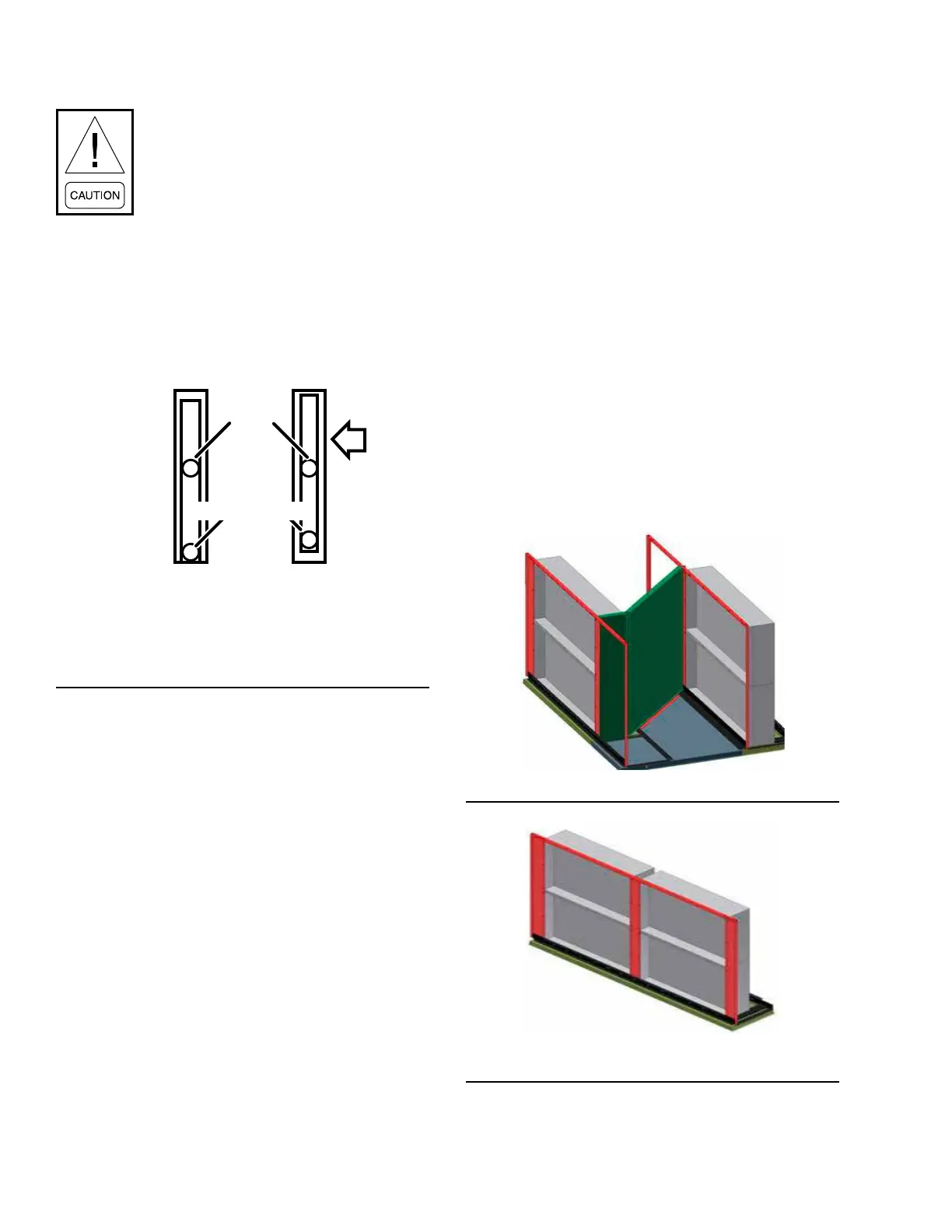
Staggered Coils
Staggered coils in the AHUs equipped with an optional
expanded cabinet will have connections brought to the
AHU exterior for liquid or steam coils as shown in Fig-
ure 116 on page 74 and Figure 117 on page 74.
DX coils are not included.
The external connections are a threaded pipe or grooved
pipe for the contractor to make his connections when
the media is liquid, or a threaded pipe when the media
is steam.
It's the installing contractor's responsibility to insulate
the piping extensions inside the AHU.
FIGURE 116 - STAGGERED COIL - ANGLED WALL
LD16561
FIGURE 117 - SPLIT COIL - OPPOSITE SIDE
CONNECTIONS
LD16562