JOHNSON CONTROLS
87
SECTION 3 - HANDLING, STORAGE, AND INSTALLATION
FORM 102.20-N1
ISSUE DATE: 7/06/2016
3
THERMOSTATIC EXPANSION VALVES (TXV)
Each coil distributor circuit requires its own thermal
expansion valves (TXV), and condensing AHU circuit
requires its own liquid line solenoid valve (LLSV).
Equip TXVs with external equalizer tubes that are field
connected to the suction line. Size the valve according
to the valve manufacturer's recommendations, allow-
ing approximately 35 psi ( throughout the coil and dis-
tributor at full load).
Do not oversize the valve. Follow the valve manufac-
turer's instructions to find the thermostatic bulb. Proper
expansion valve operation is necessary in order to real-
ize the rated coil capacity.
When a DX type coil is operated with a suction temper-
ature below 32°F, a buildup of frost will occur on the
finned surface. It is not recommended to operate DX
coils for air conditioning purposes at below freezing
suction temperatures. If the full load operating point
for the coil is selected at a safe temperature, a system
analysis is required to check for the lowest probable
suction temperature at light load conditions.
HOT GAS BYPASS (HGBP)
When using discharge air temperature control or sys-
tems with outside air economizer cooling, always in-
clude hot gas bypass (HGBP). It is not as critical to
use HGBP with return duct air temperature or suction
pressure control, but it provides better capacity control
at low loads.
The Venturi type distributor furnished with the DX
coils may be ordered for field application of an HGPB.
The connection may be made through a tee installed
in the field between the expansion valve and distribu-
tor. The system balance point and control adjustments
must assure compressor cooling and avoid excessive
compressor cycling. Refer to Guidelines for Proper
Application Piping and Split Systems (Form 050.40-
ES3) for compressor staging solutions.
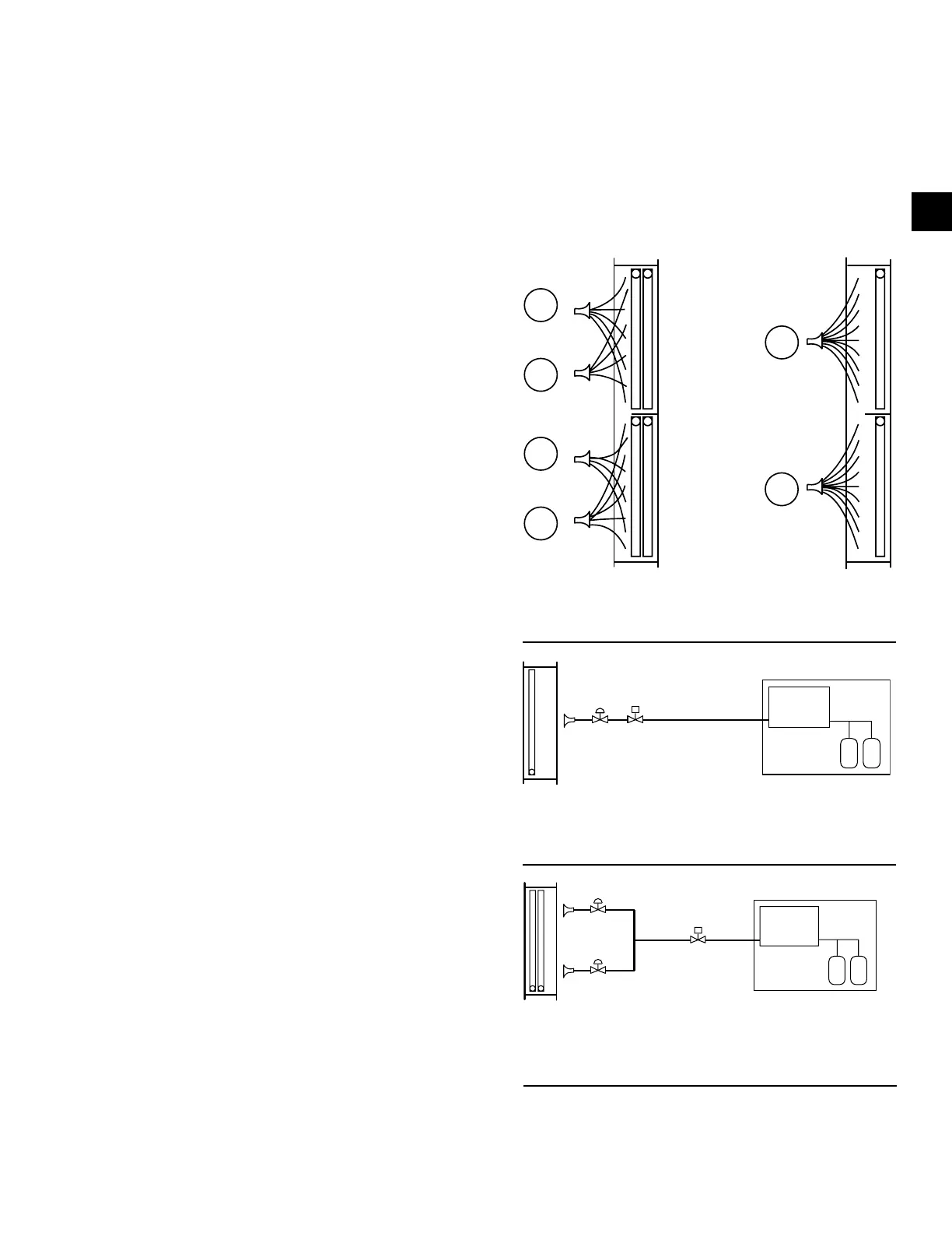
DX COIL CIRCUITING AND STAGING
On stacked coils, use a minimum of four coil circuits
to achieve full face control as shown in Figure 133 on
page 87. When the condensing AHU has two com-
pressors per refrigerant circuit, one or two coil circuits
may be used for each refrigerant circuit, depending
upon the cooling capacity.
If one coil circuit is used as shown in Figure 134 on
page 87, the LLSV and TXV must be sized to handle
the full capacity of the refrigerant circuit. When two
coil circuits are used per refrigerant circuit as shown in
Figure 135 on page 87, each TXV should be sized
to handle half of the capacity of the refrigerant circuit,
and the LLSV should be sized to handle the full capac-
ity of the refrigerant circuit.
2
4
1
3
1
2
FIGURE 133 - STACKED COIL CIRCUITING
LD09147a
Four Circuits
Recommended
Two Circuits NOT
Recommended
FIGURE 134 - ONE COIL CIRCUIT PER
REFRIGERANT CIRCUIT
LD09148
100% Capacity
DX Coil
Condensing Unit
FIGURE 135 - TWO COIL CIRCUIT PER
REFRIGERANT CIRCUIT
LD09149
DX Coil
Compressor #1
TXV
Compressor #2
TXV LLSV
Condensing Unit