FORM 155.19-EG3 (1011)
15JOHNSON CONTROLS
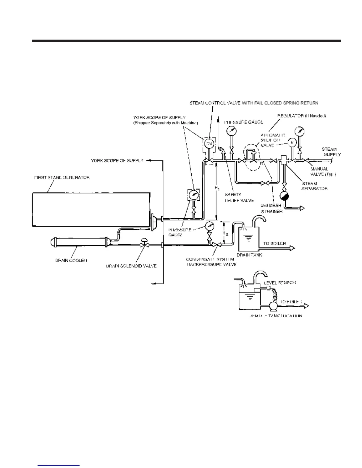
FIG. 4 – PIPING LAYOUT
NOTES:
1. H
1
= 15 in. (381 mm) minimum to prevent condensate backow.
2. H
2
= 32.8 ft. (10 m) maximum to prevent excessive back pres-
sure.
3. Condensate leaves drain cooler at approximately 15 PSIG (1 bar),
180°F (82.2°C).
4. Maximum inlet steam pressure 128 PSIG (8.83 bar).
5. Automatic shutoff valve to be failsafe type.
6. Both the steam supply and condensate drain pipes must be prop-
erly sized and pitched to prevent hammering.
7. Steam control valve to be installed within 200 inches (5 m) of the
rst-stage generator steam inlet ange.
spray header pump and one refrigerant pump.