Page 8
2.4 TECHNICAL SPECIFICATIONS - "DUALAC2&HP POWER"
Inverter for pairs of AC asynchronous 3-phase motors plus chopper for DC series pump
motor
Regenerative braking functions
Can-bus interface
Digital control based upon a microcontroller (one per each AC motor)
Voltage: .................................................................................. 24 - 36 - 48 - 72 - 80V
Maximum current (24V): ........................................ 450A (RMS) for 3' per each motor
Maximum current (36/48V): ................................... 350A (RMS) for 3' per each motor
Maximum current (72/80V): ................................... 275A (RMS) for 2' per each motor
Chopper maximum current (24V): ............................................................. 500A for 2'
Chopper maximum current (36/48V): ........................................................ 420A for 2'
Chopper maximum current (72/80V): ........................................................ 300A for 2'
Operating frequency: ..........................................................................................8kHz
External temperature range: ................................................................. -30°C ÷ 40°C
Maximum inverter temperature (at full power): .................................................... 75°C
BLOCK DIAGRAM
See chapter 2.2 - Block Diagram.
2.5 CONTROL UNIT
2.5.1 Microswitches
- The microswitches must have a contact resistance lower than 0.1ohm and a leakage
current lower than 100µA.
- When full load connected, the voltage between the key switch contacts must be lower
than 0.1V.
- The microswitches send a voltage signal to the microprocessor when a function request
(for ex.: running request) is made.
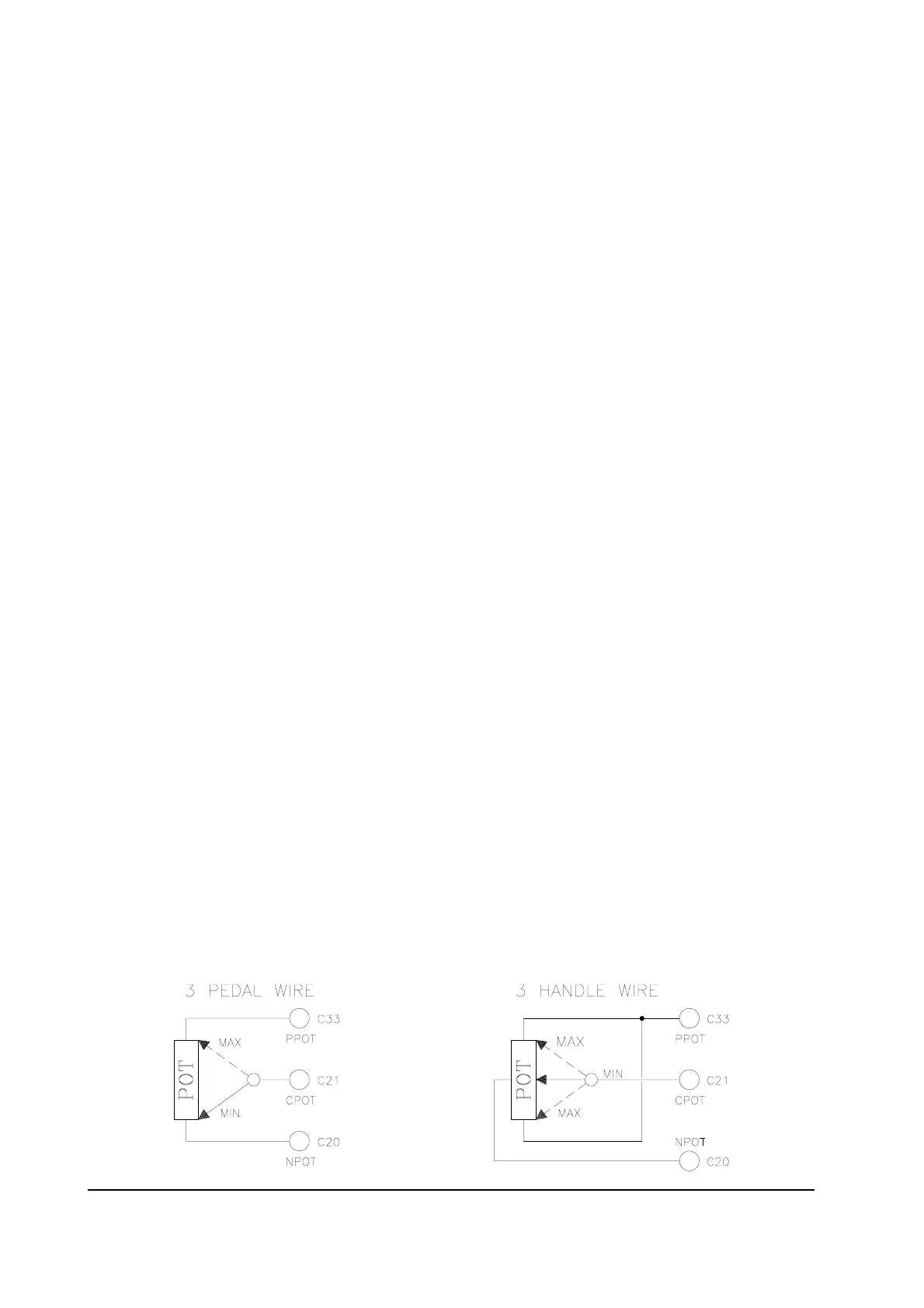
2.5.2 Accelerator unit
The accelerator unit can consist of a potentiometer or an Hall effect device.
It should be in a 3-wire configuration.
CPOT (C21) signal ranges from 0 to 10V.
Potentiometer value should be in the 0.5 - 10 Kohm range; generally, the load should be in
the 1.5mA to 30 mA range. Faults can occur if it is outside this range.