Page 9
PPOT is the accelerator unit positive supply. It can be either a 5V output or a 10V output.
The selection of the output voltage is made in the logic card by moving a jumper (factory
set).
NPOT is the accelerator unit negative supply. This output is feedback to the µC A/D con-
verter to test the continuity of the accelerator unit circuit (test of poti wire disconnection).
The Procedure for automatic potentiometer signal acquisition is carried out using the
Console. This enables adjustment of the minimum and maximum useful signal level
(PROGRAM VACC function), in either direction. This function is unique when it is neces-
sary to compensate for asymmetry with the mechanical elements associated with the
potentiometer, especially relating to the minimum level.
The sequence of procedure is described in the programming console manual.
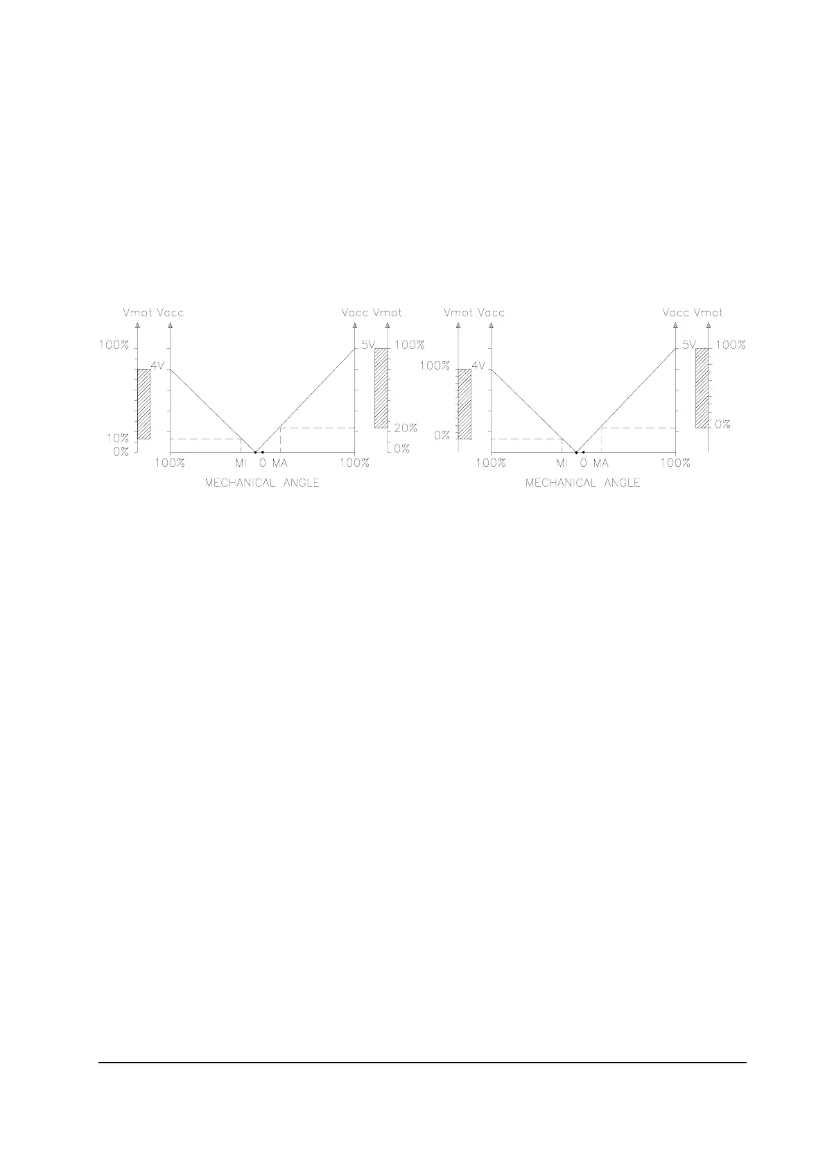
The two graphs show the output voltage from a non-calibrated potentiometer with
respect to the mechanical “zero” of the control lever. MI and MA indicate the point where
the direction switches close. 0 represents the mechanical zero of the rotation.
The Left Hand graph shows the relationship of the motor voltage without signal acquisition
being made. The Right Hand Graph shows the same relationship after signal acquisition
of the potentiometer.
2.5.3 Other analog control unit
1) Input C18 is an analog input, whose typical application is for proportional braking. It
should be in a 3 wire configuration. Potentiometer value should be in the 0.5-10 Kohm
range. Generally, the load should be in the 1.5mA to 30 mA range.
The CPOTB (C18) signal range is from 0 to 5V or from 0V to 10V.
2) Connections C25 (PTHERMR) and C24 (NTHERMR) are used for the right motor
thermal sensor. Connections C35 (PTHERML) and C34 (NTHERML) are used for the
left motor thermal sensor. Sensors can be digital (on/off sensor, normally closed) or
analog. See also chapter 5.4 for more explanation.
3) In the versions with integrated pump chopper (DUALAC2&HP and DUALAC2&HP
POWER), it is possible to input to the controller an analog signal for proportional lifting.
This input will be the output of a potentiometer (3 wires, resistance in the 1 to 10kohm
range) or of a Hall Effect device; the load must be below 10mA. CPOTLIFT (D9) signal
has to be within the 0 to 10V range.