Page 23
4.6 ENCODER INSTALLATION
1) Dualac2 and Dualac2&hp card is fit for different types of encoder. To control AC motor
with Zapi inverter, it is necessary to install an incremental encoder with 2 phases
shifted of 90°. The encoder power supply can be +5 or +12V. It can have different
electronic output.
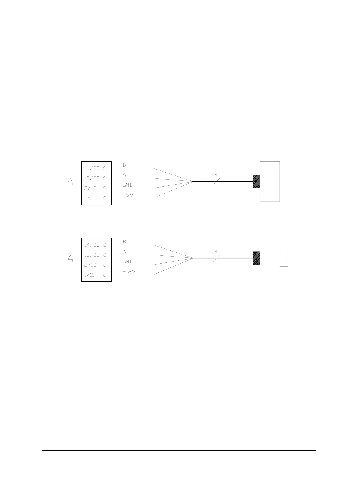
C11/C1: +5V/+12V: positive of encoder power supply.
C12/C2: GND: negative of encoder power supply.
C22/C13: A: phase A of encoder.
C23/C14: B: phase B of encoder.
2) Connection of encoder with open collector output; +5V power supply.
3) Connection of encoder with open collector output; +12V power supply.
The encoder power supply voltage and output electronic has to be communicated to ZAPI
in order to correctly set the selection jumpers in the logic card.