Chapter 4
Software Considerations
The Control Register
The
control register provides a number of functions for the Z-329 Card.
This register enables the CPU
to
communicate with the display
RAM
and
attribute
RAM,
enables video data
to
be
sent
to
the monitor, selects the
font
which
is
used, enables the blink attribute, and allows paging of the
display when the optional8K x 8 RAMs are installed.
To
control all of these functions, a single 8-bit byte
is
written into the
control register. The control register
is
located at I/O port 3B8H. The func-
tion
of each bit
is
shown
in
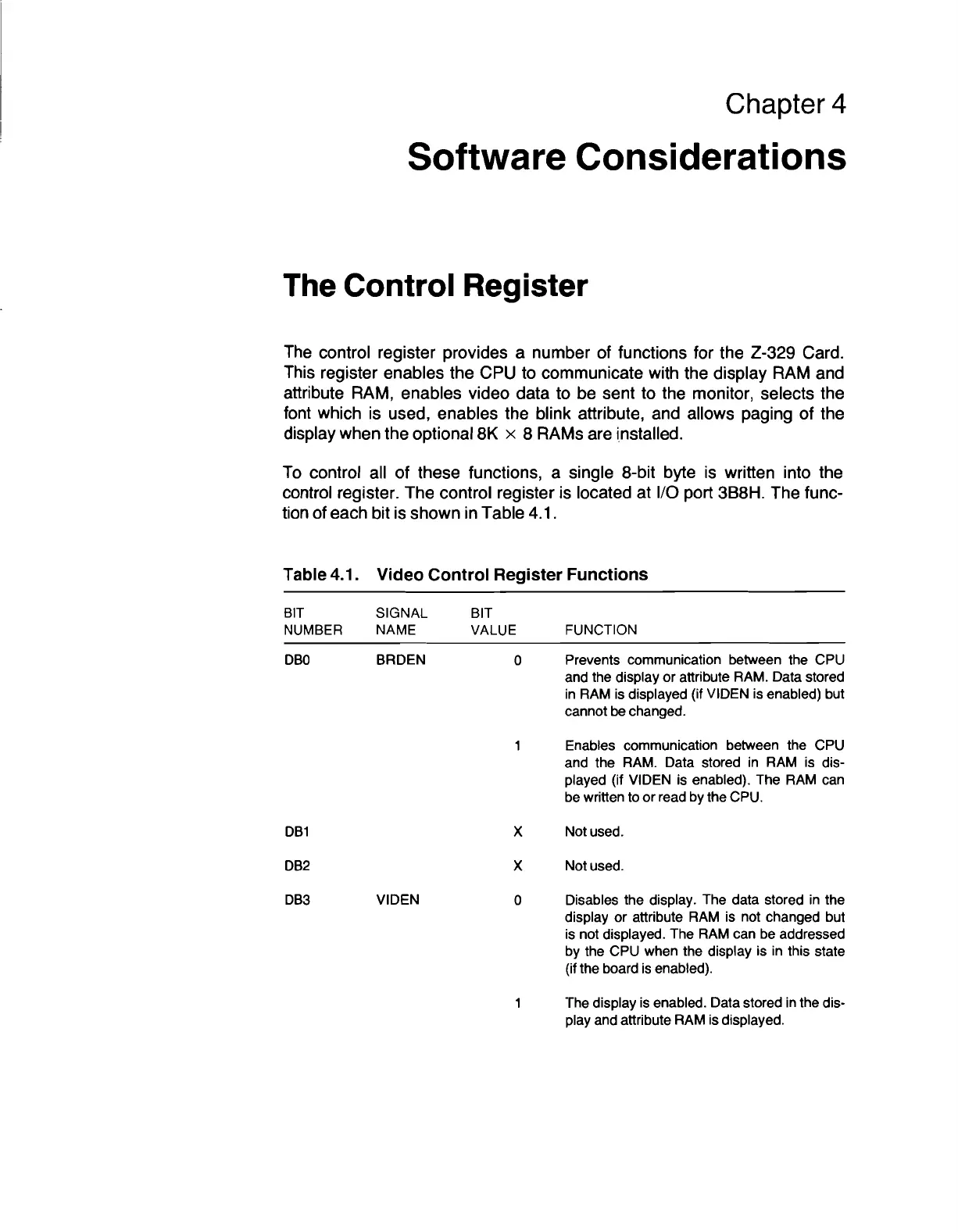
Table 4.1.
Table 4.1. Video Control Register Functions
BIT
NUMBER
DBO
DB1
DB2
DB3
SIGNAL
NAME
BRDEN
VIDEN
BIT
VALUE
o
x
x
o
FUNCTION
Prevents communication between the CPU
and the display or attribute RAM. Data stored
in
RAM is displayed (if VIDEN is enabled) but
cannot
be
changed.
Enables communication between the CPU
and the RAM. Data stored
in
RAM is dis-
played (if VIDEN is enabled). The RAM can
be written to
or
read by the CPU.
Not used.
Not used.
Disables the display. The data stored
in
the
display or attribute RAM is not changed but
is not displayed. The RAM can be addressed
by the CPU when the display is
in
this state
(if the board
is
enabled).
The display
is
enabled. Data stored
in
the dis-
play and attribute RAM is displayed.



 To Next Page