Page 5.6
Card/Circuit Description
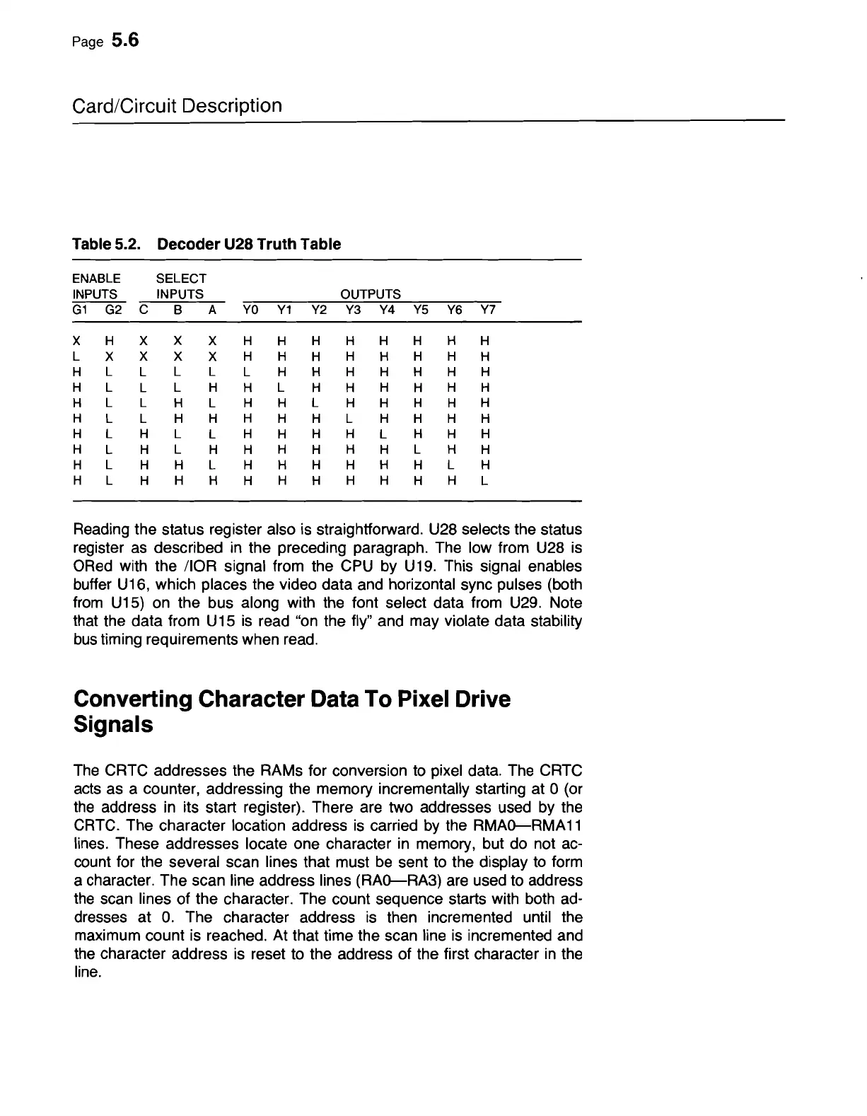
Table 5.2. Decoder U28 Truth Table
ENABLE
SELECT
INPUTS
INPUTS
OUTPUTS
G1
G2
C
B
A
YO
Y1
Y2 Y3
Y4
Y5 Y6
Y7
X H X
X
X H
H
H H H H H H
L
X
X X
X
H H
H
H
H
H H
H
H
L
L
L L
L H H H H H H H
H L
L
L H
H
L
H H
H
H
H H
H
L L
H L H H
L
H H H H
H
H
L L H H
H
H H L H H H H
H L H L
L
H
H
H H
L
H
H
H
H
L H
L
H H
H
H
H
H
L H
H
H
L
H
H L H H H H
H
H
L
H
H L
H
H H
H
H
H
H H
H
H
L
Reading the status register also
is
straightforward. U28 selects the status
register
as
described
in
the preceding paragraph. The low from U28
is
ORed
with the IIOR signal from the
CPU
by
U19.
This signal enables
buffer U16, which places the video data and horizontal sync pulses (both
from
U15)
on
the bus along with
the
font select data from
U29.
Note
that the data from U
15
is
read
"on
the fly" and may violate data stability
bus
timing requirements when read.
Converting Character Data To Pixel Drive
Signals
The
CRTC addresses the RAMs for conversion
to
pixel data. The CRTC
acts
as a counter, addressing the memory incrementally starting at 0 (or
the
address
in
its start register). There are two addresses used
by
the
CRTC.
The character location address
is
carried
by
the
RMAo-RMA
11
lines. These addresses locate one character
in
memory, but do not
ac-
count for the several scan lines that must
be
sent to the display
to
form
a character. The scan line address lines
(RAo-RA3)
are
used to address
the
scan lines of the character. The count sequence starts with both
ad-
dresses at
O.
The character address
is
then incremented until the
maximum count
is
reached. At that time the scan line
is
incremented and
the character address
is
reset to the address of the first character
in
the
line.



 To Next Page