Page
3.10
Genera.l Theory
of
Operation
• Cursor Start Register
(R10)-
This 7
bit,
write-only register
is
used
to
define the beginning position of the cursor within the character field
(scan line
0-15)
and the blink rate of
the
cursor. The 5 low-order
bits define the beginning scan line of the cursor. The size of the cursor
is
defined by both this data and
R11.
The high-order bits determine
the blink rate of the cursor
as
shown
in
Table 3.5. The default value
for this register
is
OSH
(11
decimal).
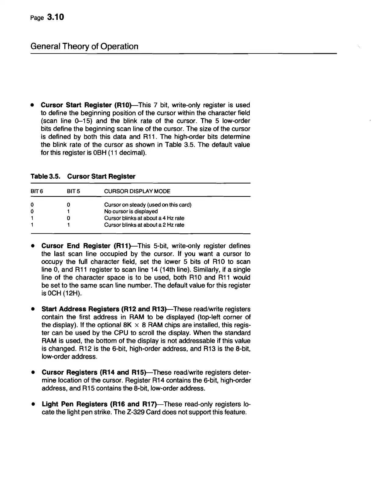
Table 3.5.
Cursor
Start Register
BIT 6
BITS
CURSOR
DISPLAY MODE
0
0
Cursoron steady (used on this card)
0
1
No cursor is displayed
1
0
Cursor blinks at about a 4 Hz rate
1
1
Cursor blinks at about a 2 Hz rate
• Cursor End Register
(R11)-
This 5-bit, write-only register defines
the last scan line occupied by the cursor. If you want a cursor to
occupy the full character field, set the lower 5 bits of
R10
to scan
line
0,
and
R11
register to scan line 14 (14th line). Similarly, if a single
line of the character space
is
to
be
used, both
R10
and
R11
would
be
set to the same scan line number. The default value for this register
is
OCH
(12H).
• Start
Address
Registers (R12 and
R13)-
These read/write registers
contain the first address
in
RAM
to
be
displayed (top-left corner of
the display). If the optional 8K x 8
RAM
chips are installed, this regis-
ter can
be
used by the CPU to scroll the display. When the standard
RAM
is
used, the bottom of the display
is
not addressable if this value
is
changed.
R12
is
the 6-bit, high-order address,
and
R13
is
the 8-bit,
low-order address.
• Cursor Registers (R14 and
R15)-
These read/write registers deter-
mine location of the cursor. Register
R14
contains the 6-bit, high-order
address, and
R15
contains the 8-bit, low-order address.
•
Light
Pen Registers (R16 and
R17)-These
read-only registers
lo-
cate the light pen strike. The 2-329 Card does not support this feature.



 To Next Page