B
H
T
21
Installation instructions
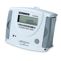
Dimensions
Height: H = 106 mm
Width: B = 126 mm
Depth: T = 54 mm
Safety instructions for installation
Read these instructions care-
fully right up to the end before
starting to mount the device! The
installation has to be done by
qualied professional personnel.
The current laws and regulations
have to be observed, especially EN
1434 part 1+6, (in Germany also
AGFW directive FW202, FW 218 and
FW 510). At devices with communi-
cation interfaces or mains supply
the general technical rules and the
correspondent regulations have to
be followed.
While demounting ow sensors
and temperature sensors make
sure no heating water escapes
from the pipe. This can cause
burns! Close valves and release
pressure before installation.
General information
Calculators for combined heating /
cooling meters can be recognized
at the imprint „change over“ or
„Heating / Cooling“ on the front of
the chassis.
Take care of:
■
The display must be readable at
all times.
■
To avoid malfunctions due
to other interferences do not
install uorescent lamps, switch
cabinets or electric devices
such as motors or pumps in the
immediate vicinity of the meter
(minimum distance 1 m).
■
All welding must be nished.
■
The ambient temperature must
not exceed 55 °C.
■
The type of temperature sensor
must correspond with the
calculator.
■
The pulse value of the ow sen-
sor must correspond with the
one from the calculator.
 Loading...