AP00001A
28.08.2018
24V 10V GND D1 E1
DC Out
(I
max
= 70 mA)
DC Out
(I
max
= 10 mA)
Digital In
Analog In
L3/NL2
L1
L1
L2 L3L1
N
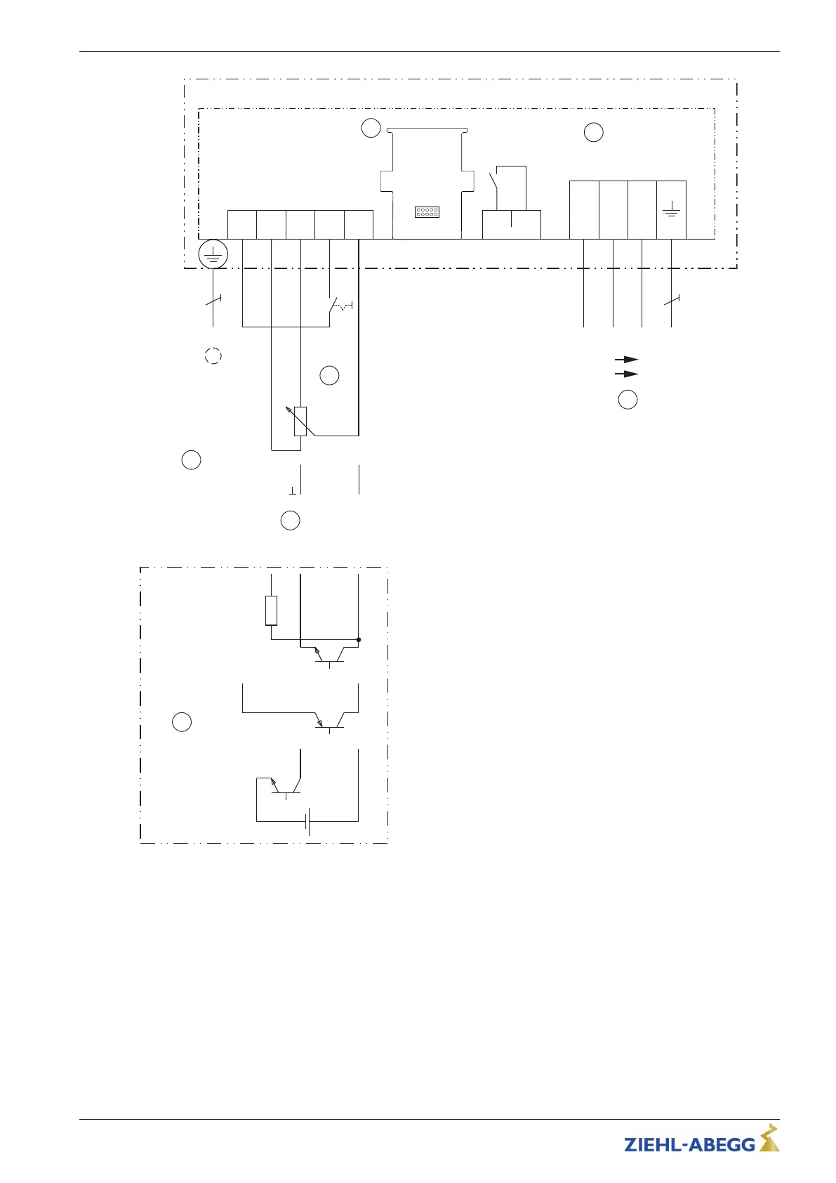
ECblue BASIC (_ _ _ _ _-_I_.D_._ _ _ _), (_ _ _ _ _-_I_.G_._ _ _ _)
K1
Netzspannung
Leistungsschild
Line voltage Rating-plate
Eingang
Input
0...10 V
4...20 mA
+
PWM
f = 1...10 kHz
Externe Drehzahlvorgabe
External speed setting
7
5
6
2
10 kΩ
10 kΩ
10 V
GND
E1
24 V
E1
E1
GND
15...28 V
+
-
1
13 14
Kontaktbelastung
Contact rating
max. AC 250 V 2 A
PE
PE
NO
AM-..
3
4
0
1
Aus / Ein
Off / On
1 Line voltage see rating plate
2 Relay output "K1" for fault reporting (factory function), max. contact load AC 250 V 2 A)
- During operation the relay is energised, i.e. the connections "13" and "14" are bridged
- In case of a fault, the relay is de-energised
- In case of a shutdown using the enable (D1 = Digital In 1) the relay remains energised
3 Slot for AM-add-on module
4 Digital enable input (factory function)
- Device "ON" when contact closed
- Device "Off" when contact open
5 External speed setting
6 Input 0...10 V, 4...20 mA
7 PWM input, f = 1...10 kHz
Quick Start Guide ECblue BASIC-MODBUS, ECblue BASIC Electrical installation
L-BAL-F078-GB 2024 Index 005 Part.-No. 00706648-GB
17/32
 Loading...