5.3 Connection versions
Each version can be supplied with an integrated AM-STICK-WB Bluetooth communication module,
and this option is indicated by the addition of “WB” to the type designation (see rating plate), e.g.
ECblue BASIC WB.
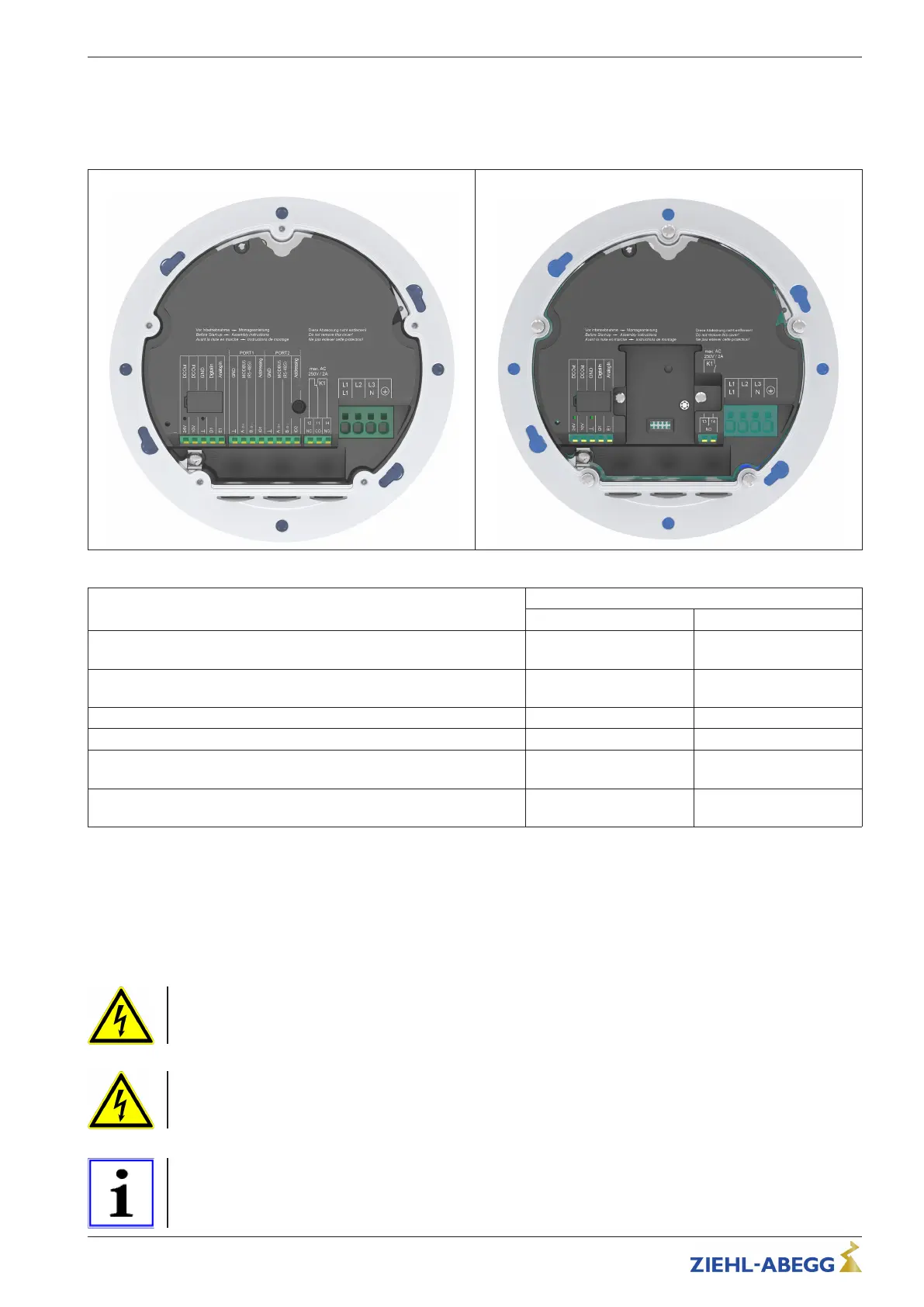
ECblue BASIC-MODBUS (ECblue MB)
ECblue BASIC
Connection options Versions
ECblue BASIC-MODBUS ECblue BASIC
Analog input for rotational speed specification via analog signal, PWM
signal, potentiometer
0...10 V, 0...20 mA,
4...20 mA, PWM, R 10 kΩ
0...10 V, 0...20 mA,
4...20 mA, PWM, R 10 kΩ
Bus interface for MODBUS (RS-485) with 2 ports, automatic address-
ing possible
X - *
Voltage supply for external devices
10 V, 24 V 10 V, 24 V
Digital input functional programmable, factory enable (device ON/OFF)
X X
Digital output functional programmable, factory fault indication Changeover contact Normally open contact
(NO)
Slot for auxiliary module with universal control function or for integration
into different networks
- X
* With AM-MODBUS auxiliary module possible
5.4 Connection diagrams
Note the following information and select the correct connection diagram for the relevant
version.
Residual-current-operated protective devices
For ECblue 3 ~ types and when connecting 1 ~ types between two outer conductors, only all-current
sensitive fault current circuit breakers (type B) are allowed (see EN 50 178, Art. 5.2).
UL: Input (Line)
Copper connecting leads with an insulation temperature of at least 80 °C must be used!
Initialisation time for relay
After switching on the line voltage, an initialisation time of a maximum 7.5 seconds is required for the
device's electronics to be operational. Subsequently, a reliable status message will be possible. If no
malfunction is detected, the relay will be energised after the initialisation time.
Quick Start Guide ECblue BASIC-MODBUS, ECblue BASIC Electrical installation
L-BAL-F078-GB 2024 Index 005 Part.-No. 00706648-GB
15/32