5.2.1 Assembly notes for cable glands
Correct use of the cable glands is of crucial importance for high operational reliability; note the
following instructions.
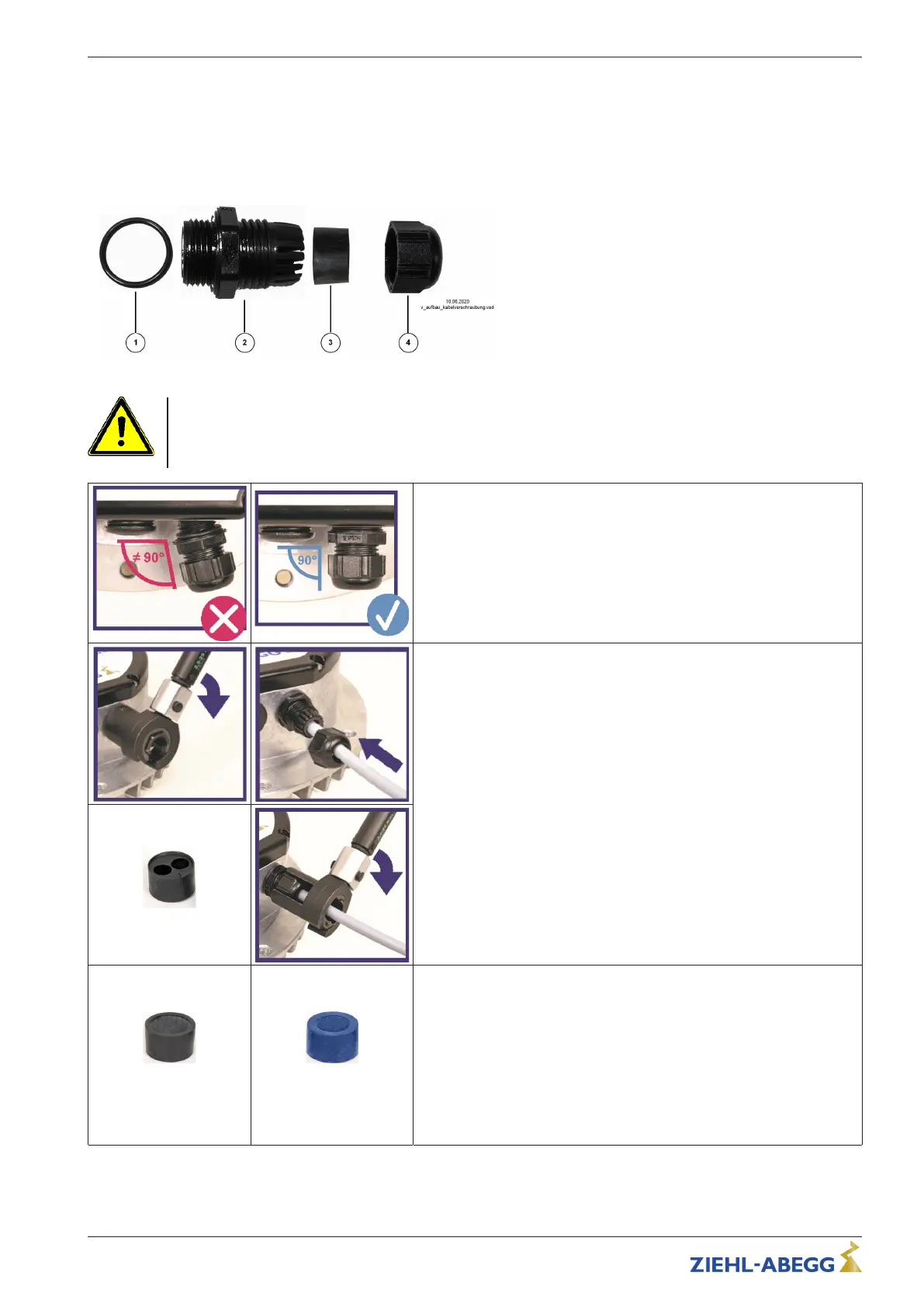
Construction of a cable gland
1. O-ring
2. Collar with connecting thread
3. seal insert
4. Union nut
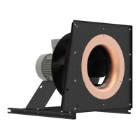
Attention!
If the tightening torque of the cable gland is too low or too high, this prevents the O-ring from having
sufficient contact with the housing and the seal insert on the cable. This results in leaks and/or poor
strain relief on the cables.
Fitting cable glands
" Select the size of the cable gland and the seal insert to match the
outer diameter of the cable.
" Check the housing for damage in the area of the sealing surface
before installing the cable gland.
" Ensure that the O-ring and seal insert are fi tted.
" Place the cable gland at a right angle on the housing and screw in.
Inserting the cable, tightening method
" Tighten the collar to the specified torque with a suitable torque
wrench.
" Insert the cable through the cable gland into the housing.
" Fit the union nut by hand and tighten slightly.
" Tighten the union nut to the specified torque of the cable gland using
the torque wrench.
" To insert two cables through one cable gland, use a seal insert with 2
boreholes.
" The seal insert supplied can only be used for a limited range of cable
diameters. It is also possible to use seal inserts with a different inner
diameter.
Seal insert for 2 cables
2 x black
Sealing area 8…12 mm
1 x blue
Sealing area 6…7.9 mm
Special feature of motor size“G” (152)
" As delivered, the 3 enclosed cable glands are fitted with one black
seal insert and two blue seal inserts.
" In addition, two black and one blue seal inserts are included sepa-
rately, and can be used if required.
Sealing areas
Black seal insert: For cables with 8…12 mm outer diameterBlue seal
insert: For cables with 6…7.9 mm outer diameter
Quick Start Guide ECblue BASIC-MODBUS, ECblue BASIC Electrical installation
L-BAL-F078-GB 2024 Index 005 Part.-No. 00706648-GB
13/32