4.2.3 Assembly of MAXvent fans type FV, DN,
For attachment to fixed motor flange use screws with property class 8.8 or A2-70 (stainless steel) to
EN ISO 4014 and provide with suitable screw locking.
Observe the following points for all types of fans:
•
Do not install without suitable supports/brackets.
•
Fasten the fan with suitable bolts using all the fastening points of the flanges.
•
Fasten the accessories with suitable bolts.
Tightening torques for fastening the fan and accessories:
Tightening torques M
A
Thread size
M6
M8 M10 M12
(Special application with
5-pitch)
Property class 8.8, friction coefcient µges = 0.12
9.5 Nm 23 Nm 46 Nm 79 Nm
Stainless steel A2-70, friction coefcient µges =
0.12
6.4 Nm 15.3 Nm 31 Nm 52 Nm
Screw penetration
≥ 1.5 x d ≥ 1.5 x d ≥ 1.5 x d ≥ 1.5 x d
When using screws with different friction values or strength classes, different tightening torques may
be necessary.
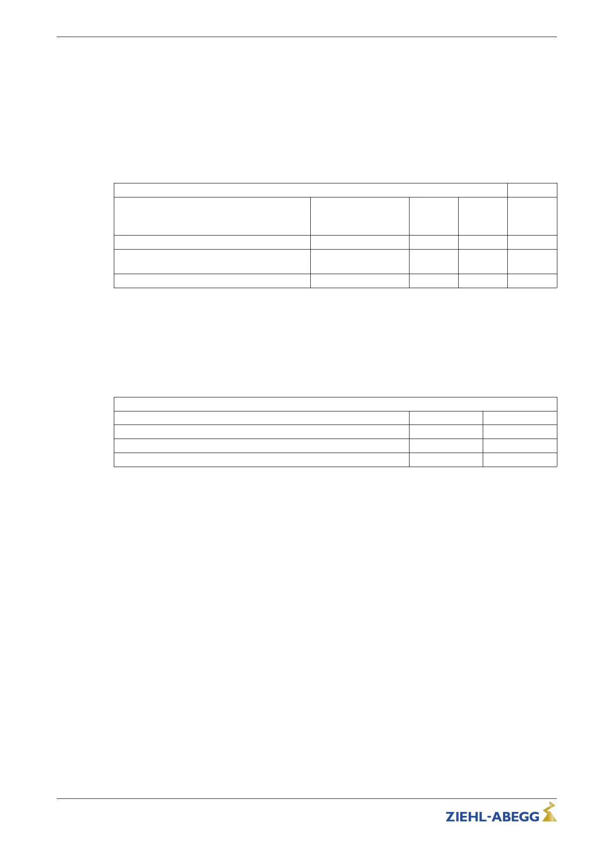
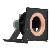
4.3 Mounting of centrifugal fans
Design RE, RH, RM, RZ
For attachment to fixed motor flange use screws with property class 8.8 to EN ISO 4014 and provide
with suitable screw locking.
Permissible tightening torques M
A
Motor size
D G
Thread size M8 M10
Property class 8.8, friction coefcient µges = 0.12
23 Nm 40 Nm
Screw penetration
≥ 1.5 x d ≥ 1.5 x d
When using screws with different friction values or strength classes, different tightening torques may
be necessary.
4.4 Mounting the motor
Motors design MK
Fastening to fi xed motor flange, see assembly of axial fans / fans of design A, D .. and assembly of
radial fans of design RH.
•
If the motor is used to drive fan impellers or other components, please note the maximum
permissible speeds of the impeller or the component to be driven.
•
The max. permissible mass of the impeller or the component to be driven must be inquired from
and confirmed in writing by ZIEHL-ABEGG.
Design K (with rotor flange) or D (with offset rotor flange) as a drive for fans:
•
During assembly of the fan impellers or other components, no inadmissible force may be applied to
the motor bearing.
•
Centre the fan impeller accurately and mount without tension on the rotor flange, the fan wheel
must lie fl at.
•
Use suitable screws for fastening the fan impeller on the rotor flange and fit as suitable screw lock.
•
Every screwing case must be tested for suitability.
•
The permissible area pressing of the steel flange may never be exceeded (depending on the
contact surface).
•
Too great a screw overhang is not permitted and can lead to scraping or blocking of the rotor on the
fixed motor flange.
Quick Start Guide ECblue BASIC-MODBUS, ECblue BASIC Mounting
L-BAL-F078-GB 2024 Index 005 Part.-No. 00706648-GB
9/32