– If the mounting height (danger area) above the reference plane is greater than or equal to
2700 mm and is not reduced by auxiliary means such as chairs, ladders, working platforms or
floor space on vehicles, a guard grille is not necessary on the fan.
– If the fan is located in danger zone, then the manufacturer or operator shall ensure that hazards
shall be prevented by appropriare protective constuctions which meet the requirements to EN ISO
13857.
•
Protective measures must be taken against falling parts when mounting with a hanging rotor.
•
Tighten the fastenings with the specified torques.
•
Drilling chips, screws and other foreign bodies must not be located inside the device! Before the first
switch-on, remove any items that may be present (drilling chips, screws and other foreign objects)
from the intake area - risk of injury from any objects that may fly out!
•
For fans, the alignment must be adhered to during operation, e.g. if this is indicated by “Oben/Top”.
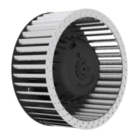
4.2 Installation of axial fans
4.2.1 Fans design A, D, K, S and W (without nozzles)
For attachment to fixed motor flange use screws with property class 8.8 or A2-70 (stainless steel) to
EN ISO 4014 and provide with suitable screw locking.
Permissible tightening torques M
A
Motor size
D D G
Thread size
M6
M8 M10
(Special application with 5-
pitch)
Property class 8.8, friction coefcient µges = 0.12
9.5 Nm 23 Nm 40 Nm
Stainless steel A2-70, friction coefcient µges = 0.12 7 Nm 17 Nm 33 Nm
Screw penetration
≥ 1.5 x d ≥ 1.5 x d ≥ 1.5 x d
When using screws with different friction values or strength classes, different tightening torques may
be necessary.
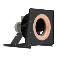
4.2.2 ZAplus fans
When mounting ZAplus fans, ensure plastic-compliant connectors.
Recommended tightening torques M
A
when using flat fastening discs according to EN ISO 7089 or DIN125
ZAplus size ((tye: ZC.., ZN.., ZF..) 040 045 - 063 > 071
Thread size
M8 M10 M12
Property class 8.8, friction coefcient µges = 0.12 12 Nm 24 Nm 40 Nm
Tightening torque guard grille fitting: 6 Nm
Information
•
Since the concrete bolt or screw varies by customer unit, these recommendations must be checked
for each respective situation.
•
Secure the cable covering against loss after connecting the motor by securing with 2 cable ties.
•
For a version with a square rear wall (design Q), removal of this square plastic plate is prohibited.
Quick Start Guide ECblue BASIC-MODBUS, ECblue BASIC Mounting
L-BAL-F078-GB 2024 Index 005 Part.-No. 00706648-GB
8/32