The MX32 cab is suitable for operation with the command station MX1 (only with SW Version 3.06).
Simply plug the MX32 in to the CAN bus socket of the MX1. The MX32 when connected to a MX1
starts in the “MX1 mode” (“MX1” in the communications dot) and will therefore have some limitations
such as: 12 functions, no RailCom, no OP PROG acknowledgements, different stop functions (see
chapter “The stop option in connection with the old MX1 command station”) and F8-F12 are sent less
frequently over the CAN bus for long loco addresses.
The MX32FU can only be used as a tethered
cab because there is no radio processor
integrated in the MX1.
The shunting key of the MX32 is inactive
with this set-up.
The usual system layout
The MX32 controller, as well as the radio version MX32FU are the most important input devices within
the ZIMO DCC system. They are used together with the current command station MX10, but also
(with reduced functionality) with its predecessors MX1, MX1HS, MX1EC.
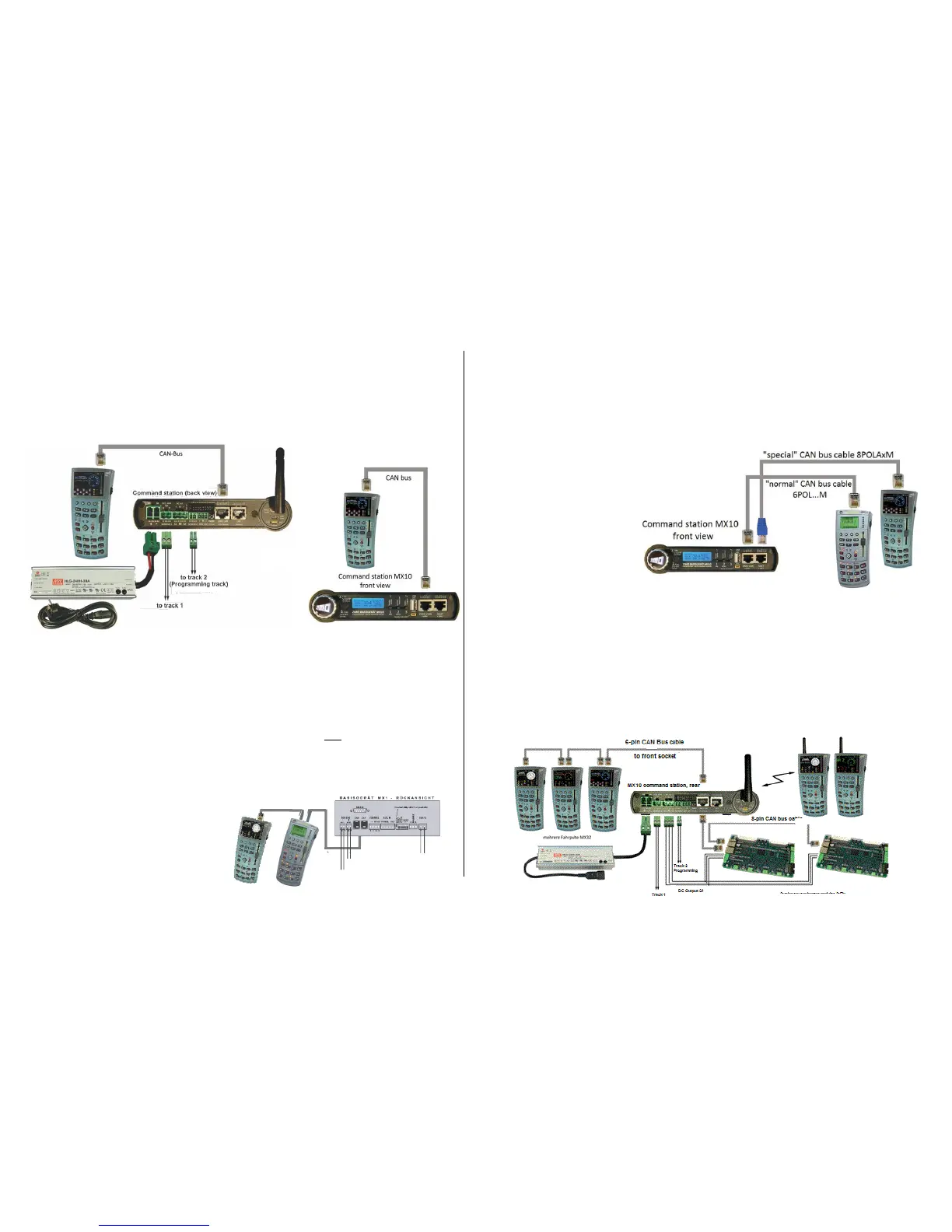
The minimum configuration of a ZIMO digital system with MX10 & MX32 is as follows:
The MX32 and MX32FU (in tethered mode) can be connected to either the front or the rear CAN socket
of the MX10 with a 6-conductor CAN cable, such as our 6POL1M (1 meter in length). Since these two
CAN sockets are internally connected to the ZIMO CAN 1 bus of the MX10, it is possible to connect
controllers to the front and rear bus simultaneously. For example, to permanently connect tethered
MX32 controllers to the rear socket, while the front socket is used to recharge the battery of a MX32FU
radio controller when needed.
The system layout with the “old” command stations MX1, MX1HS, MX1EC:
System layout with MX10 & MX32 & “old” controller types MX31, MXFU:
The following special connection scheme must be adhered to:
- The “old” devices (MX31…) must be connected with a 6-conductor CAN bus cable to one of the two
ZIMO CAN sockets (ZIMO CAN 1, either front or back of the MX10).
- The “new” devices (MX32…) must be connected to the front XNET socket (!) with a CAN bus adapter
cable (8-pin plug on the MX10’s side, 6-pin plug on the controller’s side; i.e. 8POLA1M). This special
cable connects the ZIMO CAN 2 (which is available at the XNET socket) with the CAN socket of the
controller.
The use of both CAN buses is necessary because a more
modern, faster protocol is used in the “new” command sta-
tion (MX10), which the old devices cannot communicate
with. If a device operating with the old CAN protocol is con-
nected, the MX10 automatically switches to the so-called
“MX1 mode”.
In order to use all new functions
of the MX32 without limitations
(i.e. RailCom), it must be con-
nected to the ZIMO CAN2
(XNET socket). There are no
such limitations when operating
the MX32 as radio controller.
What looks like an "illogical separation” (the “old” devices on the ZIMO CAN 1 instead of the new), is found in the neces-
sity of supplying the old controllers with about 30 V (which is only available at the “ZIMO CAN” socket), while the new de-
vices (MX32) operate with 12 V (which is available at the XNET socket). If a MX32 is to be moved from CAN1 to CAN2 it
must be turned off before reconnecting!
This connection scheme is also valid when MX7, MX8 and/or MX9 modules are to be connected. These
modules must be connected, like a MX31 controller, to the “normal” ZIMO CAN 1 socket of the MX10 and
the MX32 controllers to the CAN 2 at the XNET socket as described above.
A more extensive layout configuration with “new” devices exclusively:
The MX32FU radio controller can be operated tethered or in radio mode. In contrast to earlier ZIMO
systems, the MX10 command station has a radio module built-in and therefore DOES NOT require an
external module.
 Loading...