Technical Data
Tethered controller MX32, Radio controller MX32FU
Current consumption (with 20-30 V at the CAN bus)..…......70 mA to (while recharging battery) 300 mA
Battery in tethered MX32. ………………………………………..………………………………….. 100 mAh
Battery in radio MX32FU..…………….……………………………………………………………… 2200 mAh
Battery run-time in tethered MX32..…….……..…………………………............................................15 min
Battery run-time in radio MX32FU.. ….…………………………………………………………………….@ 5h
Dimensions Wfront – W
rear
x H
front
– H
rear
x L.............................................. …… 160 x 70 x 20 - 40 mm
Weight MX32. ................................................................................................................................... 180g
Weight MX32FU................................................................................................................................. 240g
RailCom is a registered trademark of Lenz Elektronik GmbH
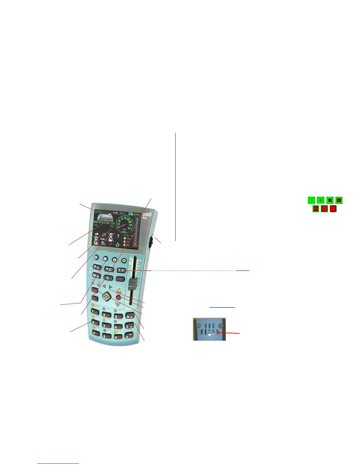
The MX32 controller in typical LOCO - Display
Display header
Current operating mode, here LOCO;
Voltage & current on the track
“Communications dot” *) for monitoring the da-
ta traffic with the command station;
RailCom logo **), when receiving data; Battery
status; Clock and fast clock.
Loco Picture
if available, change size by
tapping on the image.
Loco Name, Address, Data Format
if available; tap to increase size.
Speedo
shown here with actual speed derived
from RailCom (magenta needle) - or derived
from speed steps (blue needle);
Tap to switch to small digital speedo
(in exchange for a big loco picture)
Function key icons
shown in the numeric key pad arrangement
describe their current function and can be
operated by the actual keys or through the
touch screen. The picture shows the display
in the “Black style” (= default style).
Softkeys M (= Menu), I, II, II
current meaning above in the display.
Speed step indicator
represents the speed slider and indicates the
current speed step, loco take-over state,
speed influence and more.
Number and Function Key Pad,
also used for text input
*) The “Communications dot” indicates:
1) how quickly the command station reacts to requests from the controller by lighting up the BLUE SQUARE when, for
example, a function key is pressed, and turning it off again when a confirmation from the command station is re-
ceived. The communications dot therefore flashes only briefly; a prolonged illumination indicates a slow transmis-
sion (overloaded CAN bus, electrically limited or a poor radio link). A continuously lit dot means that the controller
commands were not executed by the command station.
2) when communication errors occur: the EMPTY SQUARE indicates by brief illumination single disturbed transmis-
sion processes (which are corrected automatically); continuous illumination means loss of connection.
**) The RailCom Logo in the display header indicates the following:
RailCom messages are sent by the decoder to the command station, where they are processed and passed on to
the controller. The flashing rate indicates the percentage of answered DCC data packets:
1:10 (i.e. the RailCom logo flashes briefly) = 1 to 5 % of the sent DCC packets were answered.
1:5 (i.e. the RailCom logo flashes a bit faster) = > 5 % to10 %
1:3 = > 10 % to 20 % 3:3 = > 20 % to 50 %
3:1 = > 50 % to 80 % 5:1 = > 80 % to 90 % permanent = > 90 %
RailCom is a registered trademark of Lenz Elektronik GmbH
****) The “Quality of Service” symbol shows the quality of the messages received from the
decoder via RailCom. This is a percentage indicator of how many DCC packets arrived
without damage from the decoder. All packets are used in this equation, not just the active
address – thereby, obtaining a fairly meaningful value as about 80 or 90 events within
one second are used as basis.
Scrolling wheel in LOCO – mode for
fine speed control (+/- 10 steps), or as a
regulator for assigned parameters (i.e. volume control).
Rocker switch (above the scrolling wheel), for an alternative
way to switch to the next or previous address or switching
between assigned parameters.
Scrolling wheel in LOCO mode with visible LoR for
scrolling among the address lines in the LoR,
Rocker switch for switching the display level.
Scrolling wheel during programing SERV PROG, OP PROG
Scrolls among lines in the CV table,
Rocker switch to increment/decrement a value.
 Loading...