Page 44 TETHERED CONTROLLER MX32, RADIO CONTROLLER MX32FU
18. Operating mode SWI
Object-oriented control of turnouts, signals…
SWI is one of two operating modes for accessory items, known as the object-oriented control of
switches and signals.
SWI …..is accessible with the W- Key
The other operating mode is the “classic” address-based control, operated from the ACC LIST (by
entering the accessory decoder address and switching the sub-address)
ACC LIST ….. is accessible with E- Key + 3 ..... or Softkey II (from the LOCO screen)
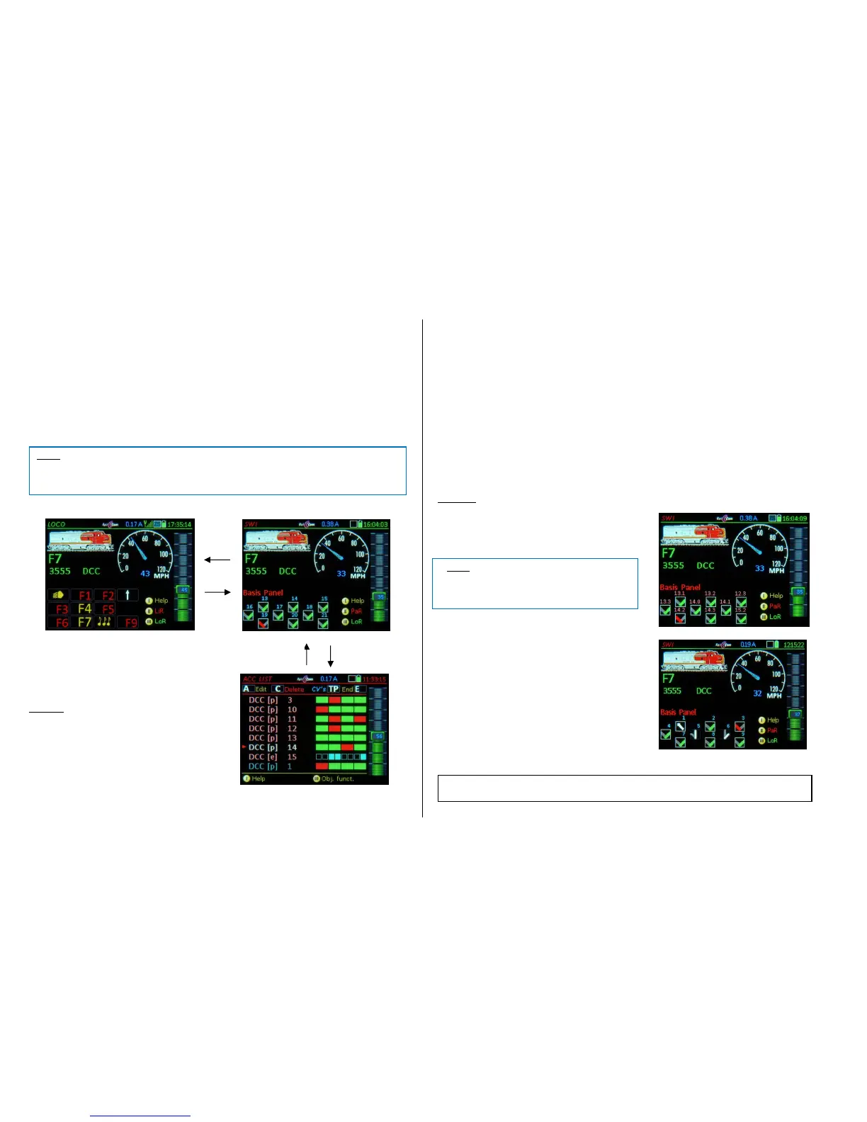
SWI is accessible from the LOCO mode and the ACC LIST with the W-Key:
In the SWI mode, the lower half of the screen is
used for turnout icons or dispatcher panels. The
panel icons represent accessory articles (the
“objects”). The function keys are assigned to the
icons in the panels (and with it to the accessory ar-
ticles) .
Example: Icon #5 Numeric key 5 (F4)
The upper half of the screen continues to show the
active vehicle, so driving is not influenced by us-
ing the speed slider and the keys Ri (Direction),
MN (Manual) and RG (Shunting). The S-Key still
operates as the stop key and F or U scroll through
the vehicles.
The numeric keys ARE NOT available as function
keys with this display.
In the object-oriented SWI mode, the function keys DO NOT control addresses of accessory decod-
ers but rather accessory articles (“Objects”). These objects must first be linked to addresses / sub-
addresses and other parameters in the SWI DEF screen, before they become operational in the panel
for turnout switching.
Entering the SWI panel for the first time opens a sample panel named “Basic Panel” in the lower half
of the screen and is displayed as follows:
Visible are 9 turnout icons, arranged in 3 rows, depicted as V-icons *). Above each icon are the icon
numbers (1, 2, 3…), which are only used to number the icons and are NOT the decoder addresses.
The whole panel made up of 18 icons in 6 rows can be accessed with the scrolling wheel.
*) These special switch icons – the “V icons” – are not copies of actual switch board symbols and do not distinguish
between right and left turnouts but rather represent the two possible positions: “right” or “left” in a simple way by
means of the direction and color of a type of switch icon. They can be replaced with other icons (see SWI DEF), such
as right and left turnouts, signals etc.
The “Basic Panel” is often sufficient for smaller applications (for up to about 30 turnouts), by adapting
it to the actual accessory articles on the layout. In the simplest case it is only necessary to change the
decoder addresses in the respective fields and to extend the panel by adding additional icons (see SWI
DEF).
For a better overview over larger layouts, it is often better to distribute the accessory articles to several
newly created panels with meaningful names, rather than using the “Basic Panel”.
Examples: “Hidden station”, “Station 1”, “Mountain side”, “Tunnel switches” etc.
(Shift)- Key displays the decoder addresses
and sub-addresses instead of the icon numbers
(MX8 are currently not supported).
Keypad actuates single turnouts or signals; alter-
natively via touch-screen by tapping on the corre-
sponding icon.
Scrolling wheel moves the panel up/down (by 1
line) to show switches 4…12 instead 1…9
The key assignment has now changed to:
Icon 5 Key 2 (F1)
Icon 8 Key 5 (F4)
 Loading...