Page 46 TETHERED CONTROLLER MX32, RADIO CONTROLLER MX32FU
Number of the icon in the panel (Object) belonging to this block
(this number cannot be changed).
1 gr | 2 rg | 3 gr | Field
Color for the function key LEDs that indicates the turnout or signal
position: r = red, g = green, y = yellow (the color is predetermined for
these icons and don’t need to be changed in most cases); Select with
rocker switch.
Icon design number (if the number is known for the desired icon it
can be entered directly to this field, using the numeric keys).
5 WLA-li | 2 V-inv | 6 WSF-re | Icon
Description of the desired icon for the panel field (permanently
linked to the number on top); immediately visible in the correspond-
ing panel field; Select with the rocker switch.
If this input field is highlighted (not the number field ahead of it), the
function keys can be used to test the looks of the icon in all posi-
tions (all icons, including the one being edited).
Rotation angle (icon orientation, the numerical entry of the desired
angle is also possible).
2 180 | 1 90 | 0 0 | Rotate
Description of the desired rotating angle for the icon; immediately
visible in the corresponding panel field; select with the rocker
switch.
Data format (DCC, MM, MX8, StEin, Q-Dec, Z-mode0, Z-mode4);
Select with rocker switch.
DCC Paired | DCC Single | MX8 Paired | Format
Paired, Single function or Sequence, for is turnouts or red-green
signals (paired functions), light bulb (single function) or multi-aspect
signals (to call up sequences of 3, 4, 5… signal aspects one by one
with one key). Select with rocker switch (“Paired”, “Single”, “Seq-3”,
“Seq-4”…”Seq-8”).
For this input field an automatic suggestion is made on the basis of
the icon selected above, a change is usually not necessary.
Enter the accessory decoder address (1…511),
MX8 address (0 … 63), or StEin address
10 0 | 10 1 | 12 3 | Sub Addr
Enter the sub-address of the accessory decoder address or the re-
spective MX8.
The following object icons are available for the switch panels. They are selected in the SWI DEF
screen within the second row of each data input block and displayed in the panel field. More icons may
be added to this basic set with future software updates.
Icon Number Label in the input block Description Graphical representations
1 V norm V-Symbol normal (default)
2 V inv V-Symbol red-green inverted
3 WLA-li Switch lantern, Left switch
4 WLA-re Switch lantern, Right switch
5 WSF-li Switch icon, Left switch
6 WSF-re Switch icon, Right switch
8 LAMPE Single light, ON/OFF function
9 SIG-2 Two aspect signal (red/green)
10 SIG-3 Three aspect signal (green/red/yellow)
When all changes in the SWI DEF are made:
W- Key Saves the newly entered data (i.e. addresses), exits the
definition screen and returns to the operating screen SWI.
E- Key Exits the definition screen WITHOUT saving, returns to the SWI mode.
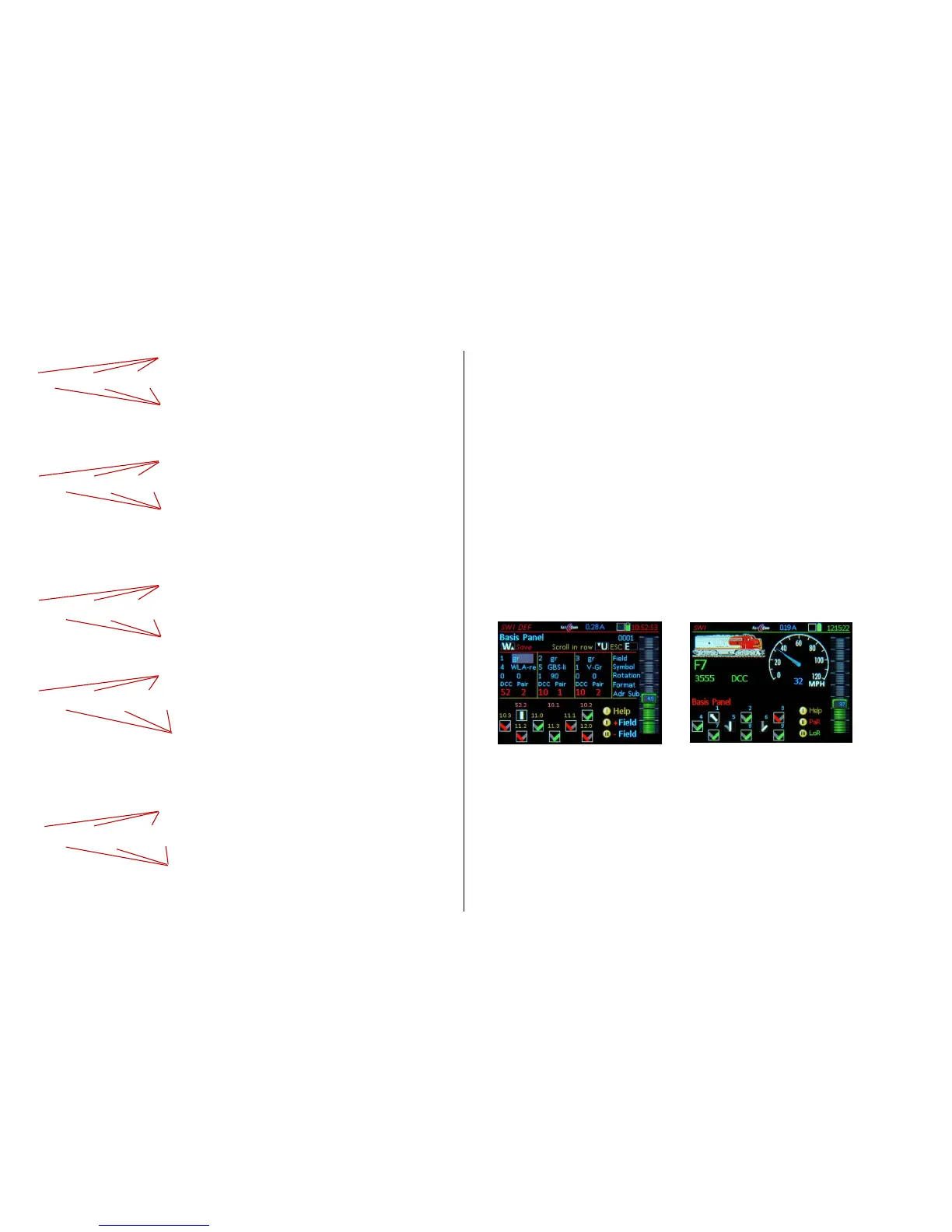
Examples of definition (SWI DEF) and operating screens (SWI) with different icons etc.
 Loading...