5.0 Preparing your wheelchair for use
5.1 Handling the wheelchair
Note - To dismantle the chair for transport or storage no
tools are required.
List of components when dismantled (components
below are related to the maximum detachable parts and
dependent on the type of seating system chosen):
1 pair of armrests
1 pair of footrests
1 backrest
1 drive unit with seat frame.
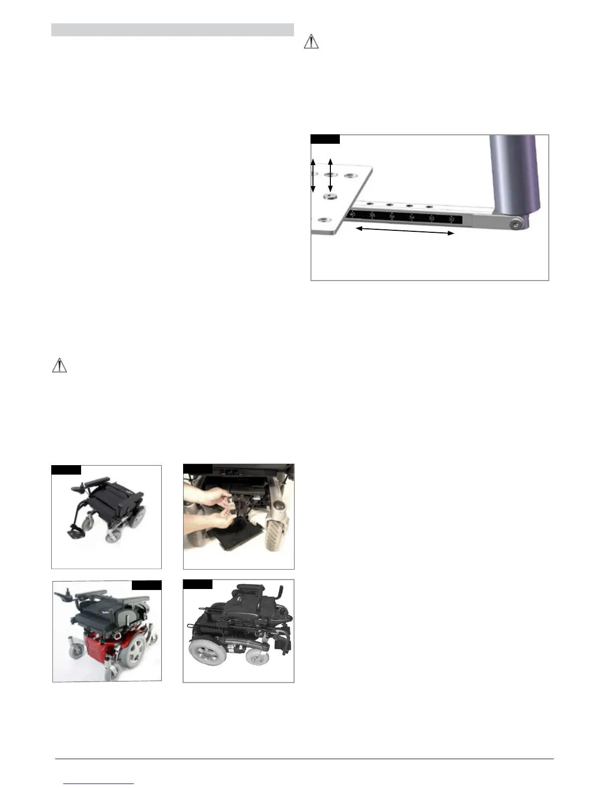
5.2 Preparation for transportation or storage
First remove the swing-away legrests. Leave the armrests
in the fold down position. (Fig. 5.1). Disconnect the Hand
Control, if necessary (Fig. 5.2). To remove the control pod
you have to access the motor controller through the plastic
cover between the castor wheels and remove the square
remote control connector.
Place the control pod & arm in a safe place until required.
To reconnect the hand control just use the process in
reverse. Release and lift off the standard backrest at the
frame (Fig. 5.3 - 5.4). Now you can store the chassis part.
By releasing the freewheel mechanism on the left and right
side of the chassis you can move the drive unit as close as
possible to the place you want to store it.
You can also drive the base with the joystick up or down a
ramp into and out of a car for transportation.
WARNINGS!
Make sure, when the chair is stored or left in the car or •
anywhere else, the controller is switched off and the
freewheel mechanisms are engaged.
If there is a need to lift the drive unit the big side frame •
tubes should be used. Caution should be taken if the
chair is in freewheel.
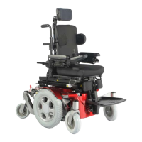
WARNING!
The Lower position of the Powered Actuator Strut MUST
correspond to the Seat depth being used, (Fig.5.8).
Following Seat depth Adjustment you MUST ensure the Lower
actuator strut position matches the seat depth set, i.e. use the
36cm Hole in the lower bracket for a seat depth of 36cm.
Fig. 5.8
Fig. 5.2
Fig. 5.1
Fig. 5.3
Fig. 5.4