1-Aug-2012
2.3 USB
2.3.1 USB OTG
ZedBoard implements one of the two available PS USB OTG interfaces. An external PHY with
an 8-bit ULPI interface is required. A TI TUSB1210 Standalone USB Transceiver Chip is used as
the PHY. The PHY features a complete HS-USB Physical Front-End supporting speeds of up to
480Mbs. This part is available in a 32-pin QFN package. VCCio for this device is 1.8V and
cannot be connected through level shifters. The PHY is connected to MIO Bank 1/501, which is
powered at 1.8V. Additionally the USB chip must clock the ULPI interface which requires an
oscillator. A Fox XPRESSO oscillator (767-26-31) is used on ZedBoard.
The external USB interface connects through a TE 1981584-1.
The usb0 peripheral is used on the PS, connected through MIO[28-39] in MIO Bank 1/501.
This USB port will not power the board. However, ZedBoard provides 5V when in Host or OTG
modes. REFCLK pin of TUSB1210 is tied to ground as the EPP will drive the CLOCK input of this
part.
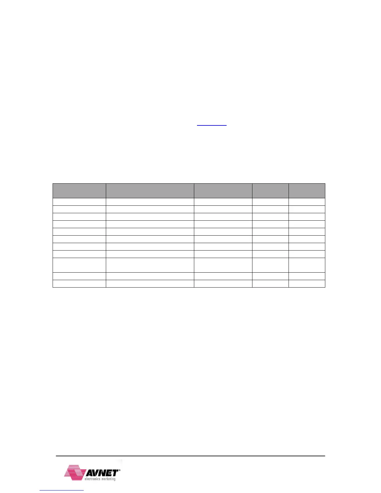
Table 5 - USB OTG Pin Assignment and Definitions
Identification pin of the USB
connector
See the Jumper Settings section for configuring the USB interface for Host, Device and OTG
mode. The jumpers control the Vbus supply as well.
2.3.2 USB-to-UART Bridge
The ZedBoard implements a USB-to-UART bridge connected to a PS UART peripheral. A
Cypress CY7C64225 USB-to-UART Bridge device allows connection to a host computer. The
USB/UART device connects to the USB Micro B connector, J14, (TE 1981584-1) on the board.
Only basic TXD/RXD connection is implemented. If flow control is required this can be added
through Extended MIO on a PL-Pmod™.
Cypress provides royalty-free Virtual COM Port (VCP) drivers which permit the CY7C64225 USB-
to-UART bridge to appear as a COM port to host computer communications application software
(for example, HyperTerm or TeraTerm). Please refer to the CY7C64225 Setup Guide posted on
zedboard.org for detailed instructions for installing the driver.
The UART 1 Zynq PS peripheral is accessed through MIO[48:49] in MIO Bank 1/501 (1.8V).
Since the CY7C64225 device requires either 3.3V or 5V signaling, a TI TXS0102 level shifter is
used to level shift between 3.3V and 1.8V.