1-Aug-2012
2.7.3 User LEDs
The ZedBoard has eight user LEDs, LD0 – LD7. A logic high on the EPP I/O causes the LED to
turn on. LED’s are sourced from 3.3V banks through 390Ω resistors.
Table 14 - LED Connections
2.8 10/100/1000 Ethernet PHY
The ZedBoard implements a 10/100/1000 Ethernet port for network connection using a Marvell
88E1518 PHY. This part operates at 1.8V. The PHY connects to MIO Bank 1/501 (1.8V) and
interfaces to the Zynq EPP via RGMII. The RJ-45 connector is a TE Connectivity PlanarMAG
(1840808-7) featuring integrated, auto-wound magnetics that enhance performance, quality and
reliability. The RJ-45 has two status indicator LEDs that indicate traffic and valid link state.
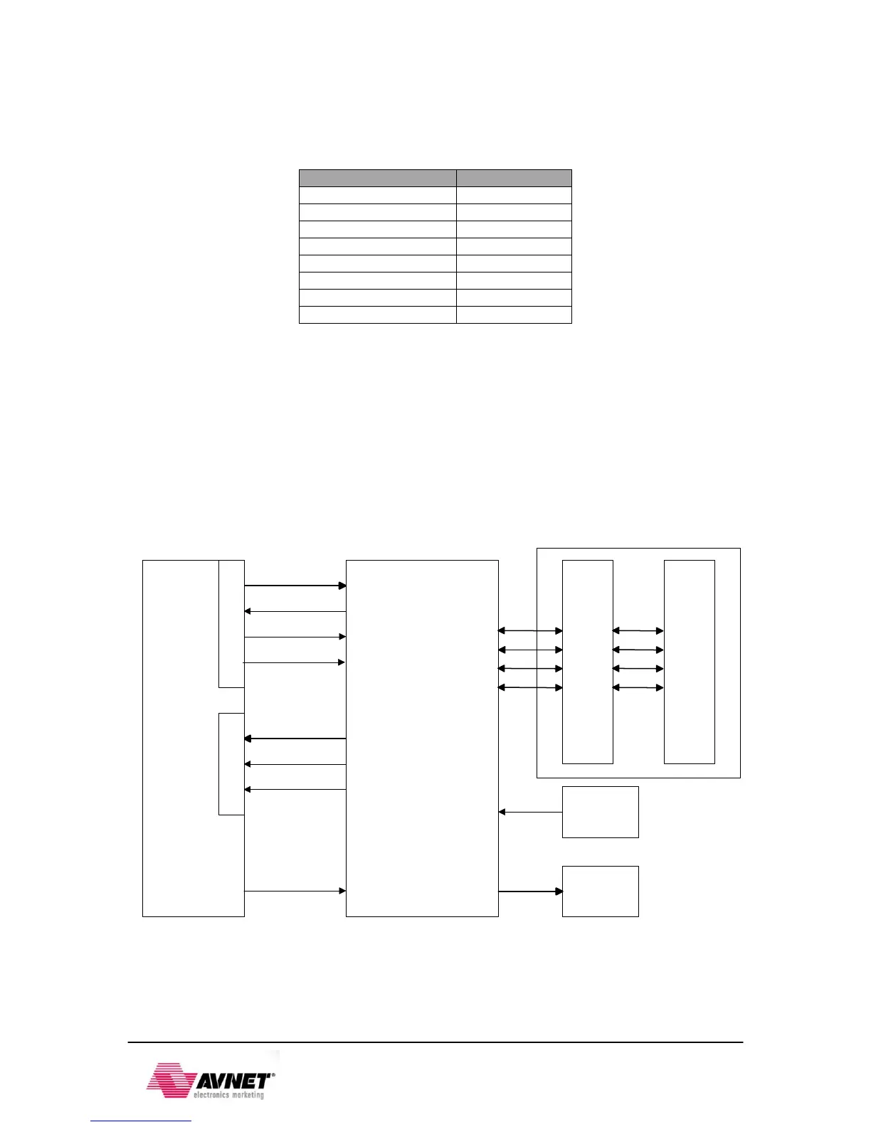
A high-level block diagram of one 10/100/1000 Ethernet interface is shown in the following figure.
data_tx[3:0]
clk_tx
control_tx
data_rx[3:0]
clk_rx
control_rx
Crystal
125Mhz
Marvell 88E1518 PHY
XC7Z020
phy_reset
TransmitReceive
10/100/1000
Magnetics
RJ45
Connector
LEDs
TD_P
TD_N
RD_P
RD_N
gtxclk
Figure 11 - 10/100/1000 Ethernet Interface
Zynq requires a voltage reference for RGMII interfaces. Thus PS_MIO_VREF, F8, is tied to 0.9V,
half the bank voltage of MIO Bank 1/501.