1-Aug-2012
2.4.4 OLED
An Inteltronic/Wisechip UG-2832HSWEG04 OLED Display is used on the ZedBoard. This
provides a 128x32 pixel, passive-matrix, monochrome display. The display size is 30mm x
11.5mm x 1.45mm.
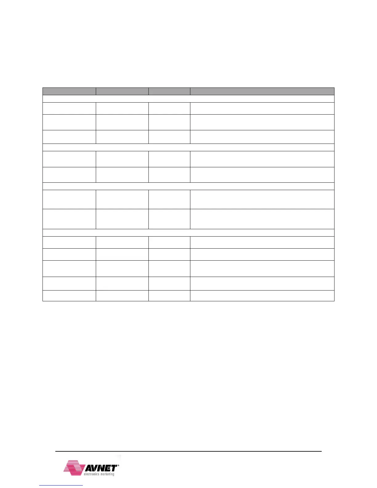
Table 11 - OLED Connections
Power Supply for OEL Panel
Current Reference for Brightness Adjustment
Voltage Output High Level for COM Signal
Power Supply for DC/DC Converter Circuit
Positive Terminal of the Flying Inverting Capacitor
Negative Terminal of the Flying Boost Capacitor
Power Reset for Controller and Driver
Chip Select – Pulled Down on Board
Serial Clock Input Signal
2.5 Clock sources
The EPP’s PS subsystem uses a dedicated 33.3333 MHz clock source, IC18, Fox 767-
33.333333-12, with series termination. The PS infrastructure can generate up to four PLL-based
clocks for the PL system. An on-board 100 MHz oscillator, IC17, Fox 767-100-136, supplies the
PL subsystem clock input on bank 13, pin Y9.
2.6 Reset Sources
2.6.1 Power‐on Reset (PS_POR_B)
The Zynq PS supports external power-on reset signals. The power-on reset is the master reset of
the entire chip. This signal resets every register in the device capable of being reset. ZedBoard
drives this signal from a comparator that holds the system in reset until all power supplies are
valid. Several other IC’s on ZedBoard are reset by this signal as well.