1-Aug-2012
2.10 Configuration Modes
Zynq-7000 EPP devices use a multi-stage boot process that supports both non-secure and
secure boot (note that secure boot is not supported for CES silicon.) The PS is the master of the
boot and configuration process. The following table shows the Zynq configuration modes. Upon
reset, the device mode pins are read to determine the primary boot device to be used: NOR,
NAND, Quad-SPI, SD Card or JTAG.
By default, the ZedBoard uses the SD Card configuration mode. The boot mode pins are
MIO[8:2] and are used as follows:
MIO[2]/Boot_Mode[3] sets the JTAG mode
MIO[5:3]/Boot_Mode[2:0] select the boot mode
MIO[6]/Boot_Mode[4] enables the internal PLL
MIO[8:7]/Vmode[1:0] are used to configure the I/O bank voltages, however these are
fixed on ZedBoard and not configurable
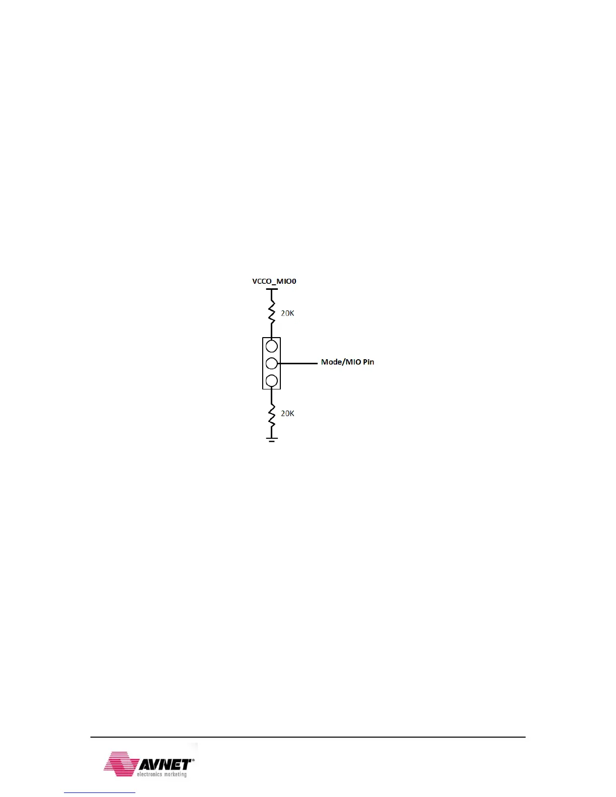
The ZedBoard provides jumpers for MIO[6:2]. These are 1x3 jumpers connected as shown
below. All mode pins can be pulled high or low through a 20 KΩ resistor.
Figure 15 - Configuration Mode Jumpers
These jumpers allow users to change the mode options, including using cascaded JTAG
configuration as well as using the internal PLL.
As noted above, the VMODE pins are strapped permanently to set Bank 500 and 501 voltages to
3.3V and 1.8V. These are not jumper selectable.