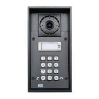
2N ® IP Verso
Basic Unit
Outputs
– digital outputoutput1
– relay outputrelay1
– red LED indicator at the panelled_secured
Inputs
– digital input on basic unitinput1
I/0 Module
The inputs / outputs are addressed as follows: , <module_name>.<input/output_name>
e.g. module5.relay1.
The module name is configured in the Module name parameter in the Hardware /
Extenders menu.
Outputs
– relay output 1relay1
– relay output 2relay2
Inputs
– digital input 1input1
– digital input 2input2
– tamper switch (if installed)tamper
Wiegand Module
The input is addressed as follows: , e.g. module2.<module_name>.<input_name>
tamper
The module name is configured in the Module name parameter in the Hardware /
Extenders menu.
Outputs
– output LED OUToutput1
Inputs
vstup LED INinput1 –

 Loading...