Front Panel 1-5
WARNING:
Use only a nonconductive object such as a plastic stylus to
press the hardware interrupt switch. Do not use the tip of a pencil.
Graphite particles can cause electrical shock to the operator and can
damage components on the server’s circuit boards.
Cover The inverted U-shaped cover is secured by two screws on the bottom
edge of each side of the chassis.
Both sides of the cover have vents. The vents on the left side (viewed
from the front of the server) are for air intake. The vents on the right
side are for air exhaust.
Front Panel
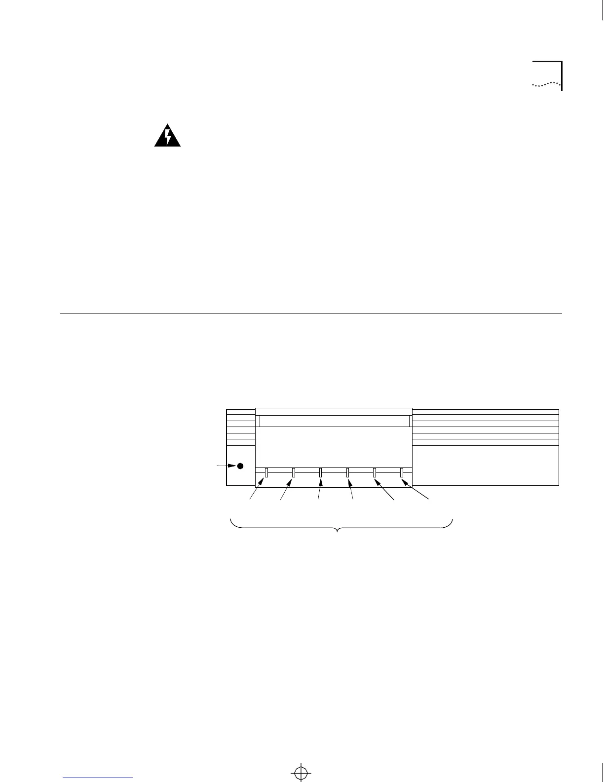
The front panel has six LED indicators and a reset switch. Figure 1-3
shows the front panel of the CS/2500 diskless server. Figure 1-4 shows
the front panel of the CS/2600, which includes a 3.5-inch diskette drive.
The front panel label shows the model number, providing easy
identification in mixed environments.
Figure 1-3 CS/2500 Front Panel
3Com
CS/2500
LED indicators
Reset
switch
Network
Activity
Data
Received
Boot
State
Self
Test
Power
Packet
Received
CS2500BookFile : Overview Page 5 Thursday, December 11, 1997 10:44 AM