RS-232 Serial Ports A-3
* Pins 11, 23, and 24 are supported on ports J0 and J1 only for synchronous modem support.
† Ring is active when server is on.
‡ Pin 25 is unused in RS-232 operation. If “Automatic RS-422 Port Selection” is enabled, port
switches automatically to RS-422 when active pin 25 is detected.
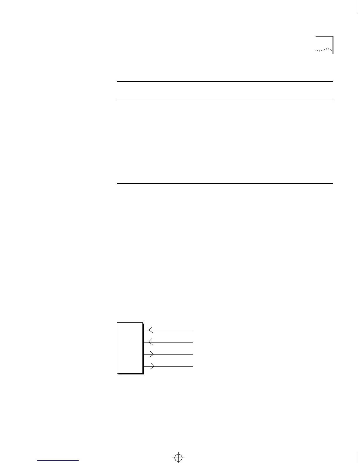
RS-422 Operation When an RS-232 serial port is configured for RS-422 operation, only
certain pins are active. When a single port is configured in firmware for
RS-422, pins 13, 14, 16, and 19 are reserved for RS-422 operation.
When all ports are configured for automatic RS-422 port selection, pin
25 is also used as a switch to detect RS-422 operation. Figure A-2 shows
cable wiring for a port configured for normal RS-422 mode. Figure A-3
shows cable wiring when all ports are configured for automatic RS-422
port selection.
Figure A-2 Cable Wiring for Serial Port in Regular RS-422 Mode
(continued)
21 — — — — Not used
22
†
— RI Out — Ring Indicator
23
*
— DTE
RXC
In — DTE Receive Clock
24
*
— DTE
TXC
In — DTE Transmit Clock
25
‡
— — — RS-232 Switch between RS-232
and RS-422 operation
Table A-1 RS-232 Serial Port Pin Assignments (continued)
Pin
RS-232-
D Name
3Com
Name
Direction
Failsafe
State
Function
DCE
CS/2500 Pin
TXD+
TXD-
RXD-
RXD+
13
14
16
19
CS2500BookFile : PinAssignments Page 3 Thursday, December 11, 1997 10:44 AM