3D Systems, Inc.
8
SITE SELECTION: ProCure™ 750 UV CHAMBER
Locating the ProCure 750 UV Chamber is similar in many respects to the ProX 800. The following abbreviated site specications
are for the ProCure UV Chamber:
4
ProCure SPACE AND LOCATION SELECTION
The ProCure UV Chamber should be located in an appropriate room or location adjoining the ProX 800. Refer to the illustration,
“Optimal Site Layout” on page 3 for a suggested overall layout. Refer to the table, “Weight and Dimensions - System
Components” on page 10 for weights and measurements, as well as the illustration, “ProCure 750 UV Chamber Dimensions”
on page 9. Consider the following additional specications when selecting the location for your ProCure unit:
Recommended oor space 7 m x 4.5 m 12 ft x 15 ft
Minimum ceiling height 244 cm 96 in
Recommended ceiling height 305 cm 120 in
Recommended clearance to ceiling 76 cm 30 in
ProCure FLOOR SURFACE REQUIREMENTS
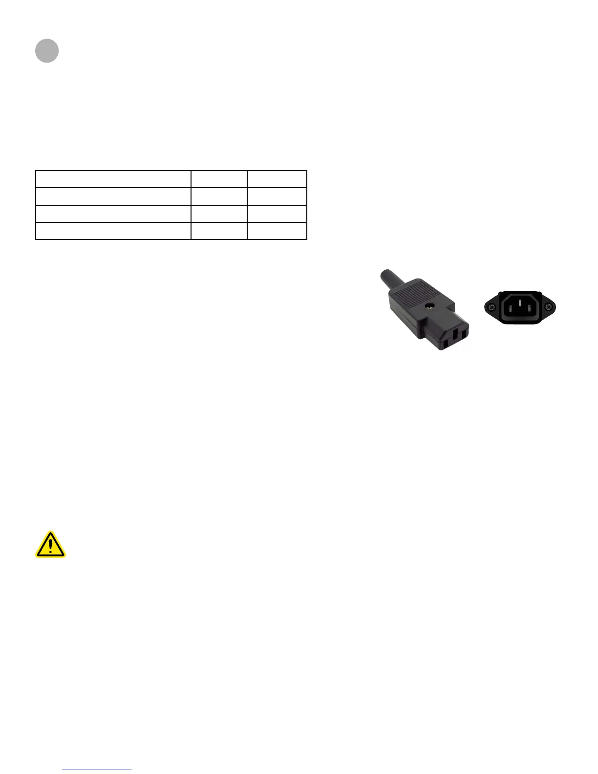
IEC 60320 C13 connector and C14 inlet are
rated 10A (VDE) and 15A (UL & CSA)
ProCure VENTILATION (DUCTWORK)
The ProCure UV Curing Chamber may be vented outside if required or appropriate. The left side of the unit has a built-in
exhaust fan, and includes an 8” diameter duct connector.
If the curing chamber duct is joined to a duct that has positive pressure, an extraction system should be installed, regardless
of duct length. Flow restriction from a 90 degree elbow equals 5.1 m (17 ft) of duct. If the exhaust run exceeds the 60 m (200 ft)
limit, an extraction system or auxiliary fan should be installed. Contact your Facilities Manager for your requirements.
Caution: Never disconnect a ducting system that is connected to an external extraction system.
Flooring under the ProCure UV Chamber should be non-porous and suitable for
cleaning with solvents. Carpeted oors are not recommended.
ProCure ELECTRICAL REQUIREMENTS
Specication - either of these two power congurations:
• 110 VAC, 50/60 Hz, 13A
• 220 VAC, 50/60 Hz, 7A
The ProCure UV Chamber is equipped with a standard IEC 60320 C14 3-wire
power cord inlet, and a USA plug with an IEC 60320 C13 outlet.
Electrical power for the ProCure UV Chamber must be on a dedicated, surge
protected circuit. We strongly recommend an Uninterruptible Power Supply
(UPS) in areas with frequent power uctuations; surges and spikes can damage
electronic components and power loss can damage the unit.

 Loading...