Do you have a question about the 3D Systems ProX DMP 200 and is the answer not in the manual?
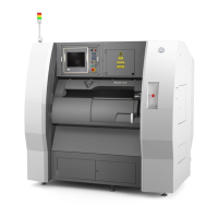
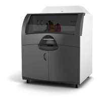
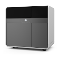
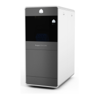
General description of the ProX® DMP200, a high quality direct metal printing machine.
Describes the step-by-step manufacturing process, from CAD file to finished part.
Specifies that laser sintering operations are performed on metal powders only.
Outlines company safety program requirements, emergency procedures, and SDS information.
Emphasizes following safety guidelines, receiving proper training, and reading instructions.
Provides guidelines for safe operation, including avoiding access to internal components and checking labels.
Stresses reading SDS before use and following handling guidelines for materials.
Warns against accessing or adjusting the laser system and entering areas with warning signs.
Advises noting machine status, clearing messages, and understanding causes of errors.
Explains safety labels indicating hazardous conditions like hot surfaces, laser radiation, and electric shock.
Provides immediate first aid guidelines for burns, electrocution, inhalation, and powder contact.
Describes how frame, enclosure, and software designs ensure a safe operating environment.
Explains interlock devices that prevent hazards like laser exposure and electrical shock.
Details how frame and enclosure designs limit access to hazardous areas for safety.
Covers software shutdown, circuit breakers, and locking keys for enhanced safety.
Lists safety features like air pressure drop detection, chamber temperature limits, and anti-collision systems.
Recommends explosion-proof wiring and highlights hazards of exposed electrical circuits.
Details required PPE like gloves, masks, safety goggles, and shoes for safe operation.
Addresses material hazards, combustion risks, and proper handling for safe operation.
Identifies metals causing health problems and those known to be combustible.
Provides guidelines for storing reactive metal powders safely, including container types and location.
General safety guidelines for handling materials, including fire/heat, inhalation, and spill prevention.
Covers inert gas use, oxygen monitoring, and risks associated with oxygen deprivation.
Discusses risks from laser-material interaction, gas use, and fume emissions.
Explains Class IV laser hazards, potential for burns, eye damage, and fire.
Focuses on eye risks from direct and reflected laser radiation.
Covers risks associated with motorized axes and inadvertent movements of actuators.
Lists and explains various safety labels found on the DMP system.
Lists all equipment provided with the ProX® DMP 200 system.
Overview of the ProX® DMP200 system components with references to detailed sections.
Describes access to the manufacturing chamber via glove ports and front doors.
Details the manufacturing chamber where direct metal printing occurs, including its window.
Lists the main optical devices including the fiber laser source and scanner head.
Explains the touch screen interface and external controls for managing the machine.
Identifies the window of the manufacturing chamber that allows viewing.
Describes the contents of the control/supply cabinet, including electrical and laser components.
Explains the function of the stack light for indicating machine status.
Describes the airlock's function for loading/unloading plates without chamber contamination.
Details the unit below the front doors controlling pneumatic and gas circuits.
Describes the external filter vessel that removes particles and fumes from the sintering process.
Step-by-step guide to safely power on the ProX® DMP200 printer.
Explains the main tool bar icons and functions available on the PX Control software.
Guides the user through preparing the printer for a job or unloading a printed part.
Allows starting the manufacturing process and monitoring its progress.
Describes the 5 user levels (Operator, Adjuster, etc.) and access restrictions.
Provides access to configuration and event browser tools for system settings.
Displays a global view of the printer's status, including preparation and tracking.
Covers essential steps before starting a job, like opening doors and checking gloves.
Instructions for unlocking and opening the printer's front doors safely.
Details the mechanism for opening and closing glove doors, emphasizing correct glove usage.
Explains how to open and close the airlock door and its positions.
Outlines procedures for servicing and replacing process filters, including safety rules.
Details the procedure for changing the lens cleaner filter, including hazards and precautions.
Provides a schedule for preventive maintenance tasks like checking air pressure and replacing filters.
Lists maintenance tasks to be performed monthly, focusing on pressure and flowrate controls.
Describes step-by-step procedures for checking gloves for damage.
Instructions for cleaning front and back casings, including safety warnings for dust and static.
Step-by-step guide for replacing the exhaust filter element, including safety precautions.
Procedure for cleaning the chiller components to prevent blockages from dirt.
Covers inspection and replacement of the clamping filter.
Details the procedure for inspecting and replacing the clamping filter.
Step-by-step instructions for replacing the gas filter, located under the front doors.
Procedure for replacing the two silicon wipers located in the manufacturing chamber.
Guide for replacing the chiller filter every 6 months.
Instructions for replacing the filter on the left door of the control/supply cabinet.
Procedure for cleaning the cabinets every 6 months.
Covers annual maintenance tasks.
Details the printer calibration procedure to correlate scanning system coordinates with print bed coordinates.
| Technology | Direct Metal Printing (DMP) |
|---|---|
| Laser Type | Fiber Laser |
| Laser Power | 200 W |
| Inert Gas System | Yes |
| Operating System | Windows |
| Connectivity | Ethernet |
| Layer Thickness | 20 - 100 microns |
| Materials | Titanium, Stainless Steel, Cobalt Chrome |
| Power Requirements | 50/60 Hz |