3D SYSTEMS, INC.
Chemical Risk ....................................................................................16
Laser Safety ......................................................................................16
Laser Safety Classifications ........................................................................16
Biological Risk ....................................................................................16
Mechanical risk ...................................................................................16
Safety labels on the DMP system ...................................................................17
Laser certification / Identification with name plate ......................................................17
Warning Labels - Airlock door ........................................................................18
Pinch Hazard Label - Front of the scanner head ........................................................18
Burn Hazard Label - Oxygen sensor ...................................................................18
Laser Safety Labels - Located on the scanner head trap door .............................................20
Laser Safety Labels - Located on the scanner head ......................................................20
Laser Safety Labels - Located on the scanner head, colimator side ........................................20
Laser Safety Labels - Located on the printer doors ......................................................20
Laser Safety Label - Located under the airlock door .....................................................21
Laser Safety Label - Located on the manufacturing chamber door ........................................21
Laser Safety Label - Located on the optical rail .........................................................21
European Directives ...............................................................................22
European directive 89/686/CE in Europe ...............................................................22
Operator safety ....................................................................................22
3
SYSTEM SPECIFICATION .............................................................................22
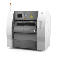
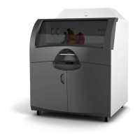
The Prox® DMP200 system .........................................................................22
4
PROX® DMP200 AT A GLANCE ........................................................................23
Prox
®
DMP200 system components .................................................................23
A. Front doors and glove doors .......................................................................24
B. Manufacturing chamber ..........................................................................24
C. Laser assembly ..................................................................................26
D. Screen control panel and external control panel .....................................................27
E. Control/supply cabinet ............................................................................28
F. Stack light .......................................................................................30
G. Airlock ..........................................................................................30
H. Pneumatic data management .....................................................................30
I. Process filter assembly ............................................................................31
Lifting ...........................................................................................32
5
SYSTEM USE .......................................................................................33
Powering up the printer ...........................................................................33
User interface ....................................................................................34
Preparation menu ..................................................................................35
Manufacturing menu ...............................................................................43
User level selection .................................................................................47
Setting menu ......................................................................................48
Machine Status menu ...............................................................................54
Machine preparation ..............................................................................56
Introduction .......................................................................................56
Plate preparation and loading .......................................................................58
Zero sintering search ...............................................................................60
Loading the feeding piston ..........................................................................60
Creating the powder bed ............................................................................61