Do you have a question about the 3D Systems ProX 800 and is the answer not in the manual?
Lists topics covered: documentation, safety, components, software, operations, maintenance, support, and glossary.
Lists related documents like Facility Guide, Material Guides, MSDS/SDS, and Software Docs.
Covers General Safety, Laser Safety, Labels, Chemical Safety, and Environmental Conditions.
Illustrates and describes printer components: MDM, Print Applicator, Printhead, UI.
Details software operation and the process of creating a print.
Instructions for maintenance, troubleshooting, and customer support.
Defines terms related to the ProX 800 and its operations.
Details facility requirements for installing the ProX 800 3D Printer.
Details the use of materials certified for the ProX 800.
Information on material safety, handling, and hazards.
Information on 3D Sprint software for preparing CAD models.
Explains symbols for hazards like damage, shock, radiation, and irritants.
Lists important safety procedures for operating the ProX 800.
Details the UV laser used and its classification as a Class I product.
Describes Master Power Shut-off and Emergency Stop buttons.
Explains the blue LED indicating the laser status on the user interface.
Indicates locations of laser safety labels on the system.
Explains how interlocks prevent laser exposure when doors are opened.
Shows and explains TÜV Rheinland and CE Mark safety certification labels.
Details the label on the rear with model, S/N, and voltage information.
Shows the internal view of the chamber controller panel.
Shows the internal view of the AC electronics panel.
Highlights the main power disconnect switch for safety.
Advises wearing gloves, goggles, and protective clothing for handling materials.
Discusses hazards of photopolymers and where to find MSDS/SDS.
Guidelines for storing materials, including protection from light and temperature.
Procedures for regulated material disposal and spill cleanup.
General first aid and protective equipment recommendations for material exposure.
Recommended room temperatures for optimal printer operation and part quality.
Optimum humidity levels and altitude limits for part quality.
Specifies the overall sound pressure level of the equipment.
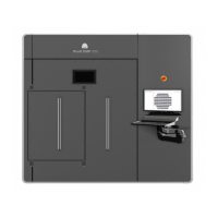
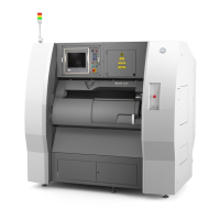
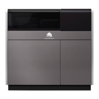
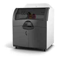
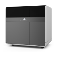
Overview of external components: Light Stack, Printhead, E-Stop, UI, Status Lights, Door Handle.
Details internal components like E-Stop, Print Pad, Elevator, Omron Sensor, Print Applicator.
MDM docking pull pin, guide rails, chamber lights, and safety interlocks.
Electrical cabinet, inner panel, power disconnect, and system controller.
Describes Print Mode and Stand-by Mode for the MDM.
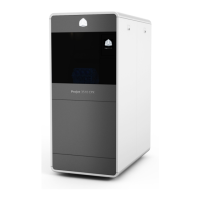
Details MDM models, capacity, and smart cartridge technology.
Identifies MDM basin, lid, release lever, connectors, brakes, and material bin.
MDM heater switch, container release, fill pump, and leveling reservoir.
Describes the Image Print Module and Laser Controller.
Details LEDs indicating system status: Fault, Ready, Standby, Laser On.
E-Stop function and the touchscreen for printer control.
Controls for chamber lights, laser status, system enable, and USB ports.
Explains the meaning of Laser, Control, and System LEDs.
Locks doors and resumes operations after E-Stop or fault.
Indicates E-Stop, fault condition, or aborted print job.
Indicates printer servicing, user warning, or E-Stop.
Indicates print job progress or manual operation.
Accessory for removing and transporting the print pad with large parts.
Describes the tablet's home screen and launching the Print3D Pro application.
Tabs for Status, Prints, Materials, Tools, Settings and alerts.
Google Search Bar, Voice Input, Status Icons.
Displays printer name, alerts, progress, and navigation tabs.
Buttons for Start/Stop/Restart and Unlock Door.
Shows current settings, material temp, recoat style, and job timing.
Preview window of the 3D model being printed.
Displays print job names, status, and queue management options.
Buttons to Start/Stop/Pause, Restart, Refresh, and Unlock Doors.
Organizes print history by month for easy access.
Shows job details and options to copy to queue or delete.
Options to move job in queue, to history, or delete.
Shows material type, expiration date, batch number, and level.
Displays the weight of material in the leveling reservoir and refill container.
Toggles the printer doors between Lock and Unlock positions.
Manually operates the elevator leveler and print applicator.
Accesses Printhead settings and initiates printer shutdown.
Controls for moving elevator to Home, Start, Offload, or Stirring.
Displays current/start/offload positions, move distance, velocity, stir time/depth.
Controls for applicator movement: Home, Move, Vacuum, Remove Bubbles, Calibration.
Displays applicator current position, move distance, and velocity.
Controls for shutter, spot size, IPM beam movement, and laser ON/OFF.
Displays beam positions, IPM power, and movement values.
Navigates to the manual printer connection screen.
Displays printer identification and software build details.
Displays network configuration details like IP address and DHCP.
Navigates to view and set printer and MDM heater temperatures.
View and edit scale factors for accurate part printing.
Controls for Auto Drain and Smart Sweep features.
View and set imaging system center point (X/Y values).
Prompts for IP address to set up network connection manually.
Shows printer name, serial number, build version, and build date.
Shows IP address, MAC address, hostname, DNS, gateway, and DHCP status.
View and set temperature for the chamber heater.
View and set temperature for the MDM heater.
View and edit scale factors for accurate part printing.
Saves the current scale settings.
Controls auto-drain for lifting print pad after print.
Confines sweeper motion to the print area.
View and set imaging system center point (X/Y values).
Provides user control over restarting interrupted builds.
Wizard for making mid-build recoat adjustments.
Modifies recoat parameters and adds recoat ranges.
Option to change layer rendering style via App Settings.
Simplifies the process of stirring print material in the MDM.
Information on obtaining and installing the 3D SPRINT software.
Overview of the 3D Sprint software interface.
Procedures for installing and removing the print applicator.
Periodic cleaning of the print applicator with isopropyl alcohol.
Detailed steps for installing the MDM into the printer.
Connecting I/O, Serial, and Power connectors for the MDM.
Procedures for safely moving the MDM out of the machine.
Explains online/offline heating and operating temperature.
How the system adds material from containers.
Detailed steps for inserting and securing material containers into the MDM.
Detailed steps for removing material containers from the MDM.
Adjusts the distance for moving the print pad.
Detailed instructions for setting the print pad's start position.
Checks print pad, launches software, verifies door locks, homes elevator.
Steps to remove bubbles from the material using the applicator.
Loads print files, selects job, and starts the print process.
Allows excess resin to drain off the part(s).
Procedures for installing the print platform without the offload cart.
Procedures for installing the print platform with the offload cart.
Steps to safely remove the print platform without the offload cart.
Steps to safely remove the print platform using the offload cart.
Emphasizes protective gear and proper disposal of waste material.
Cleans parts in TPM and IPA using a RAMCO system.
Removes supports, rinses, dries, UV cures, and smooths parts.
Wipes outer surfaces with a clean, dry, lint-free cloth.
Requires qualified technician; includes charcoal filter replacement.
Procedures for trained operators to maintain printer functionality.
Refers to the Print Applicator Cleaning section on page 49.
Lists necessary tools and preparation steps for tubing replacement.
Detailed steps for removing and replacing the pump tubing.
Location of the PC Reset button for rebooting the computer.
Actions for power outages and proper system shutdown procedures.
Table listing symptoms, causes, and actions for troubleshooting.
Identifies various connectors on the power panel.
Identifies circuit breakers (CB) and contactors (K).
Identifies terminal blocks (TB) and relays (CR).
Table detailing component load ratings and functions.
Visual representation of electrical components and connections.
Diagram showing connections for elevator, VAT, CCB, and other components.
Details required information before contacting support.
Contact numbers for US, Canada, UK, EMEA, and International.
States service must be by certified technician; provides contact numbers.
Emphasizes certified technicians for laser service due to injury risk.
Copyright information and proprietary rights of 3D Systems, Inc.
Compliance with FCC rules for digital devices and interference.
Compliance with RFID regulations and FCC IDs.
Identifies manufacturer, address, product description, model, and serial number.
Declares conformity to Machinery and EMC Directives.
Lists standards used for conformity declaration.
Defines beam profile and the device used to measure it.
Defines layer border vector and printer data files.
Defines cured material thickness and material dripping process.
Describes Z-stage component and light energy absorption.
Defines polymer building block and safety data sheets.
Describes process of monomer conversion to polymer.
Describes laser assembly and material application system.
Equipment used to produce stereolithographic parts.
Defines material container and directed line segment for slices.
| Brand | 3D Systems |
|---|---|
| Model | ProX 800 |
| Category | 3D Printers |
| Language | English |