3D Systems, Inc.
19
Inner Electrical Panel
to the material surface along the length of the print area. The sensor calibrates the position of the applicator so that it
moves perfectly parallel to the material surface, enabling the print to be accurate and precise. The applicator system
uses the motion axes that are connected to the applicator, enabling the system to self-calibrate and permitting a
customized setting of the applicator gap, or distance from the applicator’s bottom to the material surface, for different
materials. For instructions on removing and replacing the applicator, refer to the section “Print Applicator Installation
and Removal” on page 48.
MDM Docking Pull Pin: The pull pin is used to fasten the MDM into place in the print chamber. See the instructions for
installing and replacing the MDM in the section “Material Delivery Module (MDM) Installation” on page 49.
MDM Guide Rail: There are two guide rails on opposite sides of the print chamber which are used for directing the
MDM into and out of the print chamber. Refer the section “Material Delivery Module (MDM) Installation” on page 49.
Chamber Lights: There are two chamber lights inside the print chamber. These can be turned on or off from the
“Chamber Lights” button on the UI as well as the switch on the light itself. For more information, see the section “User
Interface” on page 24.
Safety Interlock: Safety interlocks are used to ensure that doors and panels are not improperly opened during
printing and other printer operations. Safety interlocks must be satised for many printer operations.
Electrical Cabinet: The electrical cabinet houses the system computer and the main power disconnect switch, as well
as other controller hardware for the printer.
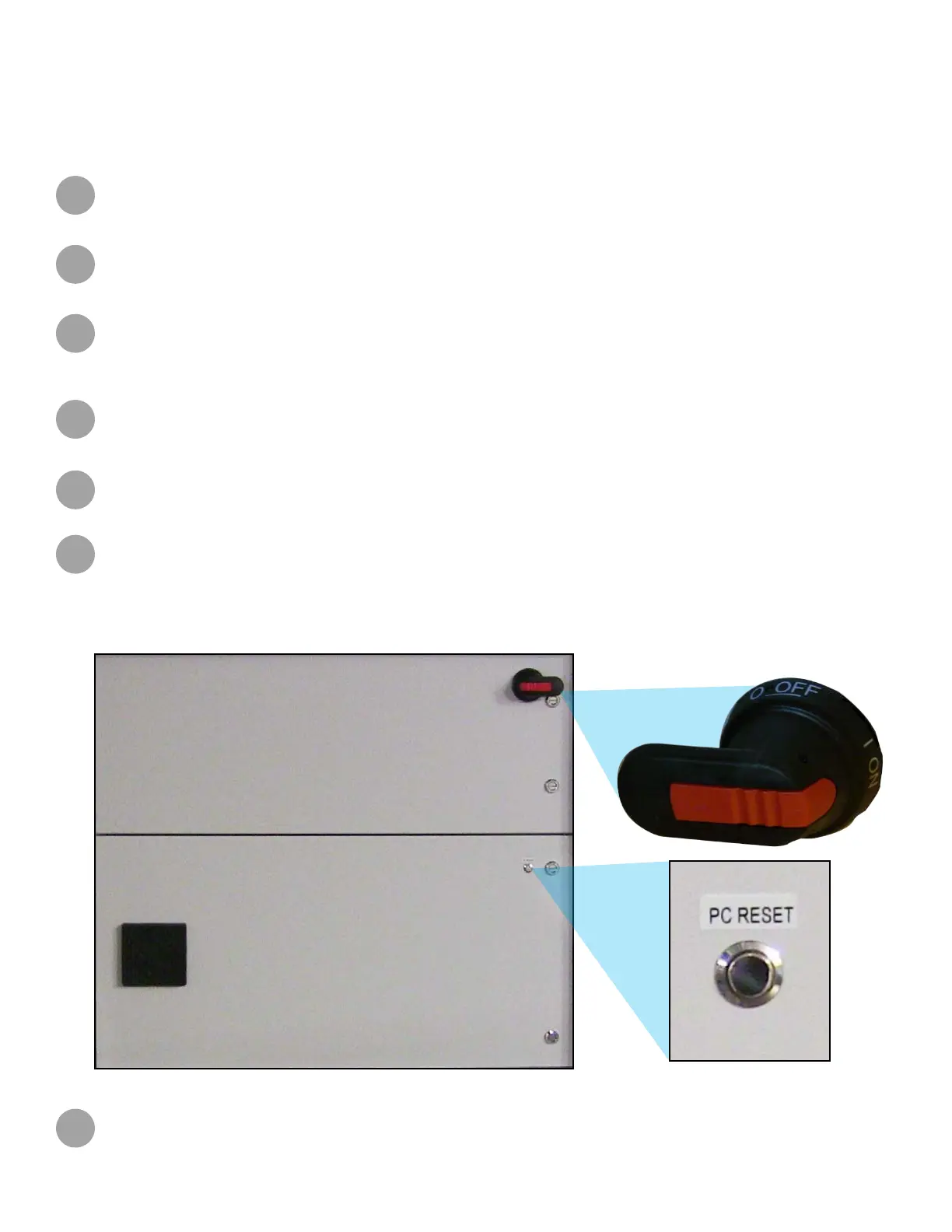
Inner Electrical Panel: This is located behind the outer panel of the printer. It contains the following items:
Main Power Disconnect: The disconnect enables you to turn on or off all power to the system. For safety reasons,
the machine should be positioned to allow easy access to this switch.
PC Reset Button: The reset button resets the system’s controller.
F
G
H
I
J
K
System Controller: A computer which controls the printer is located inside the electrical cabinet. The user does not
have direct access to this device. The touchscreen user interface provides all user functionality.
L