303D SYSTEMS, INC.
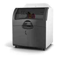
F. Stack light
The stack light provides information about the status of the machine at any given time:
• Green continuous: machine available,
• Flashing green: manufacturing,
• Flashing orange and green: manufacturing error
• Flashing orange: unlocking / cycle break / initializing,
• Orange continuous: STOP
• Red continuous: emergency / stop
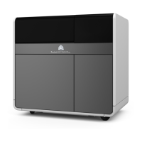
G. Airlock
The airlock lets operators load/unload a plate and powder cans without
having contact with the inside of the chamber, thus ensuring there is no
contamination of the powder and maintaining the inerting process.
The airlock is located behind the front doors.
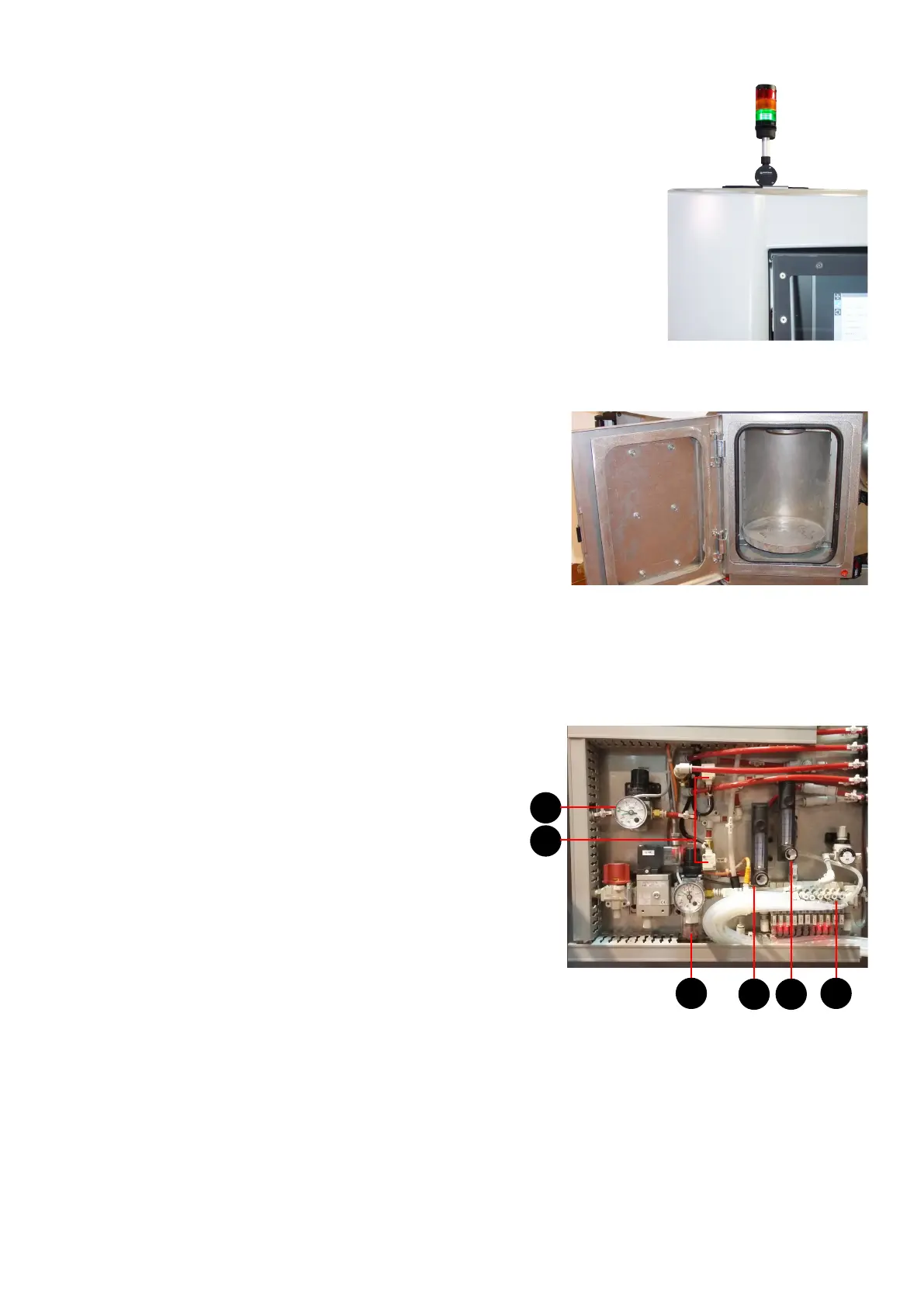
H. Pneumatic data management
This unit is located below the front doors of the printer. It contains all the systems required to control input to pneumatic
and gas circuits.
Pneumatic circuit containing:
• an air treatment unit (manual shut-off valve, solenoid valve,
lter, regulator) (A),
• a pump island (B),
• an air injection ow regulator in the chamber to ensure a high
O2 level (default value set to 0) (C).
Gas circuit containing:
• a pressure regulator (D),
• two solenoid valves that control operation of the chamber's gas
feed and purge system according to the selected case (E),
• a gas ow regulator to adjust ow rate in control mode (F).
A B
D
E
F C