3D Systems, Inc.
3
SITE SELECTION - ProX 800
This section provides the requirements and recommendations to determine the most appropriate location for a highly
functional, ecient ProX 800 workspace, with room for other equipment and supplies.
To help you choose a location, refer to “Appendix A: Initial Site Survey Checklist” on page 16. This checklist provides the
attributes that you need to select the best location for your installation.
After narrowing the list of possible locations, consider each requirement carefully before making a decision about your nal
placement site.
3
SPACE REQUIREMENTS
User preferences, building codes, and equipment
conguration help you to dene the total oor
area that your ProX 800 will need. The SLA system
should be located in an environmentally controlled
room. Locate the secondary post processing
equipment and supplies in an adjoining room
or rooms, if possible. User preferences, building
codes, required storage space, and other factors
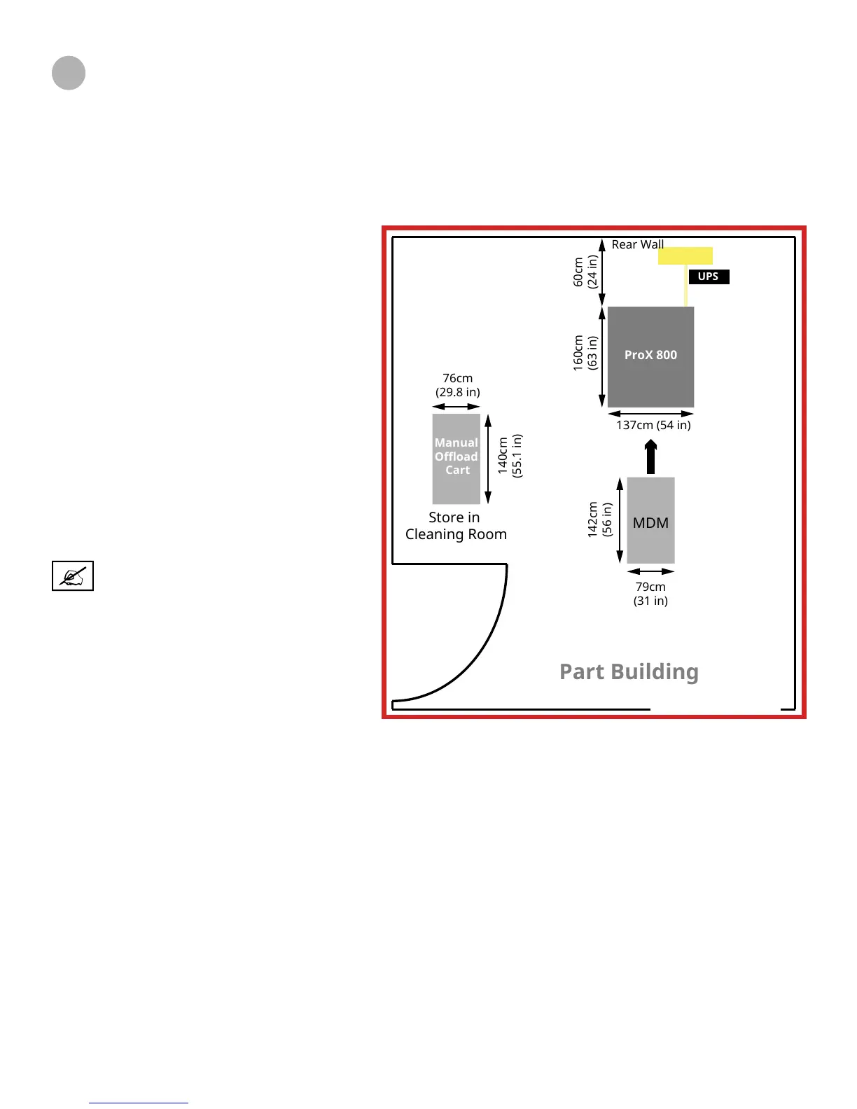
inuence total room area. The illustration at
the right shows an ideal site conguration that
minimizes the required movement of parts after
printing. To leave ample room for access to the
rear of the unit, set the ProX 800 24in (60cm) away
from the rear building wall.
The illustrations, “ProX 800 system space
requirements” on page 4 show the minimum
dimensions of the ProX 800 system. Your site
layout will vary.
NOTE: Due to laser safety requirements,
the system should be located where
access to the room can be avoided
during service calls.
Optimal Site Layout
FLOOR AREA/SURFACE
Floors and counter spaces in the SLA work area should be non-porous and suitable for cleaning with solvents. The feet of
the system must be on a non-resilient surface such as bare concrete. Carpeted oors must not be used. Remove any ooring
where the feet of the SLA system will be placed. The system should not straddle any oor seams. The maximum permissible
oor incline is 2.5cm/12m (1 in/40 ft).
FLOOR VIBRATION AND SHOCK
To ensure part quality and accuracy, choose a ground oor location with a thick concrete pad, which will minimize vibration.
SLA equipment is slightly self-damping, and should not be affected by normal or incidental environmental vibration; however,
the area should be isolated, either via location or some other physical or mechanical means, from any signicant internal or
external vibration sources such as heavy machinery, airplanes, or trains, which could cause unacceptable shock or vibration
levels.
It is recommended that the amount of vibration/shock from the oor not exceed the SPIE 1991 VC standards of VC-A. This
corresponds to a max oor velocity of 50 m/sec over a 4-80Hz bandwidth. Users are responsible verify the level of vibration in
their facility.
Power
UPS
Part Building
ProX 800
MDM
Manual
Offload
Cart
Store in
Cleaning Room
60cm
(24 in)
160cm
(63 in)
142cm
(56 in)
140cm
(55.1 in)
137cm (54 in)
76cm
(29.8 in)
79cm
(31 in)
Rear Wall