10
3-SAFETY (continued)
2014 June
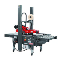
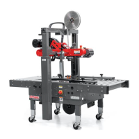
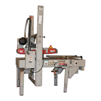
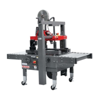
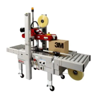
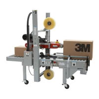
Refer to Figure 3-9 below to acquaint yourself with the various components and controls of the case sealer.
Also refer to Section 7 for controls, valves, and switch locations and Manual 2 for taping head components.
Figure 3-9 7000r/7000r3 Pro Case Sealer Components (Left Front View)
7000r-7000r3 Pro - NA
3.12 Component Locations
Upper
Taping
Head
Electrical/Pneumatic
"On/Off" Switch
w/Circuit Breaker
Box
Centering
Guides
Infeed End
Centering Guide
Air Pressure
Regulator
Box Centering Proximity Sensor
(inside box)
Upper Drive
Assembly Switch
(with Proximity Sensor)
Upper Drive Belts
Lower Drive Belts
Lower Taping Head
Emergency Stop Switch
Column Guards
Pneumatic
Controls
Air Pressure Regulator,
Centering Guide Force
(upper assembly air pressure
counter balance)
Upper Drive
Pressure
Gauge
Upper Drive
Assembly
Release Knob
Push Button Station
"Start/Stop"
Electrical
Control Box
 Loading...