29
For boxes which are fully packed with products that
support the top fl aps, the adjustment of this regulator is
not critical since the boxes can support the pressure of
the upper frame (drive belts) at a wide range of regulator
settings. However, if under-fi lled or fragile boxes are to
be sealed, this regulator can be used to set the upper
frame to a higher pressure that is adequate for conveying
the box through the machine while also allowing the
upper assembly to descend on box and preventing box
damage.
Note – A precision regulator is used to balance the
upper drive assembly. Due to the self relieving
feature of this regulator a small amount of
air will continually vent to the atmosphere.
This is normal and amounts to approximately
3 liter/min [0.1 SCFM ].
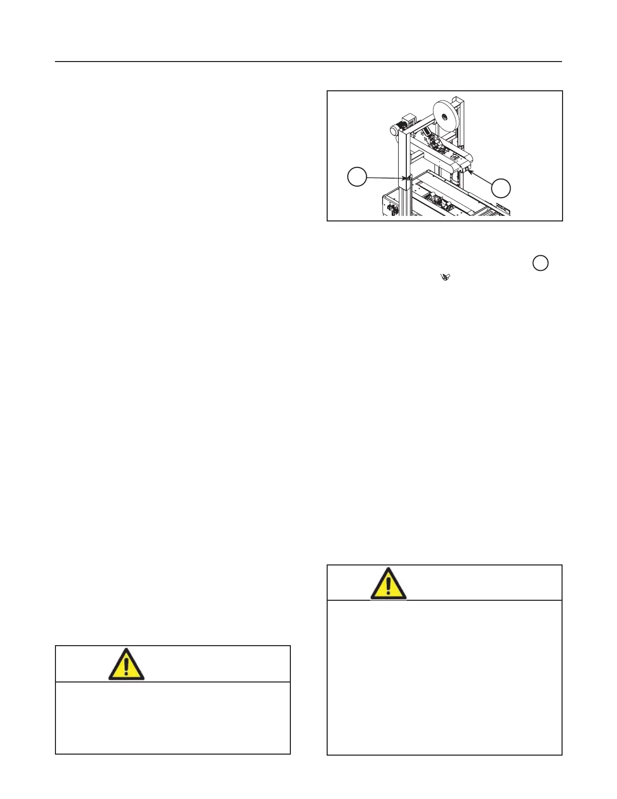
Figure 7-17
Mechanical Latch
8. Main Air Pressure Gauge - Indicates main air regula-
tor pressure setting. Air regulator should be adjusted
so gauge reads 5 bar gauge pressure [70 PSIG].
9. Mechanical Latch, Upper Drive Assembly
(Figure 7-17)
The mechanical latch is provided to hold the upper
drive assembly at the fully raised position for tape
threading and maintenance.
To raise and latch the upper drive assembly:
1. Push and hold upper frame raising switch "A".
2. Push and hold latching knob "B".
3. Release switch "A".
4. Release knob "B".
5. Shut off air supply.
To release and lower the upper drive assembly:
1. Turn on air supply.
2. Push and release switch "A".
B
A
7-INSTALLATION AND SET-UP (continued)
Important – Before turning drive belts on, be sure
no tools or other objects are on the
conveyor bed.
• To reduce the risk associated with
pinch and entanglement hazards:
− Always feed boxes into the machine by
pushing only from the end of the box
− Keep hands clear of the upper head
support assembly as boxes are
transported through the machine
• To reduce the risk associated with
pinch and impact hazards:
− Keep away from the pneumatically controlled
upper drive assembly and box centering
guides when air and electric supplies are on.
CAUTION
CAUTION
• To reduce the risk associated with
pinch and entanglement hazards:
− Keep hands, hair, loose clothing, and
jewelry away from moving belts and
taping heads
2014 June
10. Upper Drive Pressure Gauge
As indicated in Air Pressure Regulator / Gauge,
Upper Drive Assembly Force Adjustment ,
The Upper Drive Pressure Gauge is used as an
indicator of "counter balance force" that equal-
izes air pressure on the Column Cylinders and
keeps Upper Assembly from dropping too quickly
from the raised position. Adjust the force higher (+)
or Lower (-) to equalize and create this balance.
11. Electrical Control Box - Houses DC Power
Supply for Proximity Sensors, Control Relays,
Motor(s) Contactor, and opening delay timer for
Box Centering Guides.
12. Push Button Station "Start/Stop"
Controls Box taping Cycle / Starts and Stops
Drive Belts.
7
7.16 Tape Loading/Threading - See Manual 2 or 3.
Note – If lower tape drum is mounted in alternate lower
outboard position, remove taping head from
machine bed by pulling straight up, insert threading
needle in taping head and replace taping head.
Install tape roll on drum (adhesive on tape leg up),
thread tape under knurled roller on outboard
mount, then attach tape to threading needle and
pull tape through taping head with threading needle.
 Loading...