10-SAFETY DEVICES OF THE MACHINE
36
10.1 Blade Guards
Both the top and bottom taping units have a blade
guard. (See Manual 2 or 3: AccuGlide™ 3 Taping
Heads - 2 Inch or 3 Inch).
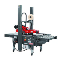
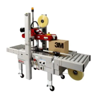
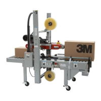
10.2 Emergency Stop Button
The electrically driven box drive belts and pneumatics
are turned on and off with the switch on the side of the
machine frame.
- The machine electrical supply can be turned off by press
ing the latching emergency stop switch (Figure 10-1).
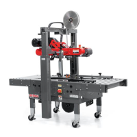
- To restart machine, rotate the emergency stop switch
clockwise to release the switch latch.
Restart machine by turning the On/Off switch to the Off
position and then to the On position (Figure 10-2).
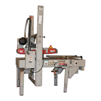
- Then press the Station "Start" Button (Figure 10-3)
.
10.3 Electric System
The electric system is protected by a ground wire
whose continuity has been tested during the fi nal
inspection. The system is also subject to insulation
and dielectric strength tests.
2014 June
7000r-7000r3 Pro - NA
Important: The use of an extension cord is not
recommended. However, if one is
needed for temporary use, it must:
• Have a wire size of 1.5mm diameter [AWG 16]
• Have a maximum length of 30.5m [100 ft]
• Be properly grounded.
Note: The case sealer has a circuit breaker
located in the electrical enclosure on the
machine frame. If circuit becomes overloaded
and circuit breaker trips, unplug the machine
electrical cord and determine cause of
overload. After two minutes, reset the circuit
breaker. Plug machine electrical cord into
outlet and restart machine by Turning the
On/Off switch to the On position.
• To reduce the risk associated with
hazardous voltage:
− Position electrical cord away from foot
and vehicle traffi c.
• To reduce the risk associated with sharp
blade hazards:
− Keep hands and fi ngers away from tape
cutoff blades under orange blade guards.
The blades are extremely sharp.
• To reduce the risk associated with
mechanical and electrical hazards:
− Allow only properly trained and qualifi ed
personnel to operate and service this
equipment.
WARNING
WARNING
WARNING
"On-Off"
E-Stop
"Start/Stop"
Figure 10-1
Figure 10-2
Figure 10-3
 Loading...