10
1.0 PRODUCT APPLICATION
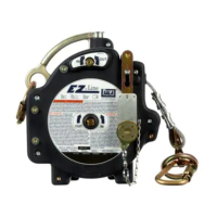
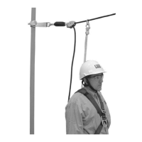
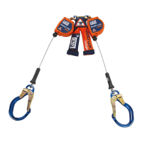
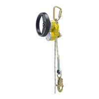
1.1 PURPOSE: The R550 Rescue & Escape Device is intended to lower one or two people simultaneously from an elevated
height to a lower level in a rescue situation. Multiple people may descend one after another using the device. The descent
speed is automatically limited during descent. Models incorporating a hand wheel allow for raising persons a short
distance to facilitate rescue (1m).
;
Rescue Only: This device is for use in rescue situations only. Do not connect Lifting Equipment to the R550 Rescue
& Escape Device and do not use the device for any purpose other than for rescue.
1.2 STANDARDS: Your R550 Rescue & Escape Device conforms to the national or regional standard(s) identied on the front
cover of these instructions. If this product is resold outside the original country of destination, the re-seller must provide
these instructions in the language of the country in which the product will be used.
1.3 SUPERVISION: Use of this equipment must be supervised by a Competent Person
1
.
1.4 TRAINING: This equipment must be installed and used by persons trained in its correct application. This manual is to be
used as part of an employee training program as required by CE, and/or regional regulations. It is the responsibility of
the users and installers of this equipment to ensure they are familiar with these instructions, trained in the correct care
and use of this equipment, and are aware of the operating characteristics, application limitations, and consequences of
improper use of this equipment.
1.5 RESCUE PLAN: When using this equipment and connecting subsystem(s), the employer must have a rescue plan and
the means at hand to implement and communicate that plan to users, authorized persons
2
, and rescuers
3
. A trained,
on-site rescue team is recommended. Training should be provided on a periodic basis to ensure rescuer prociency. Team
members should be provided with the equipment and techniques necessary to perform a successful rescue. Rescuers
should be provided with these User Instructions.
1.6 INSPECTION FREQUENCY:
The R550 Rescue & Escape Device shall be inspected by the user before each use and,
additionally, by a competent person other than the user at intervals of no longer than one year.
4
Inspection procedures
are described in the “Inspection and Maintenance Log” (Table 2). Results of each Competent Person inspection should be
recorded on copies of the “Inspection and Maintenance Log”.
1.7 AFTER A FALL: If the R550 Rescue & Escape Device is subjected to the forces of arresting a fall, it must be removed
from service immediately, clearly marked “DO NOT USE”, and then either destroyed or forwarded to 3M for replacement or
repair.
2.0 SYSTEM REQUIREMENTS
2.1 ANCHORAGE: The structure on which the R550 Rescue & Escape Device is placed or mounted must meet the Anchorage
specications dened in Table 1.
2.2 DESCENT PATH AND LANDING AREA CLEARANCE: The planned descent path must be unobstructed. The landing
area must be clear of obstructions to permit safe landing of the user. Failure to provide an unobstructed descent path and
landing area may result in serious injury. Maintain a minimum distance of 31 cm away from any vertical surface to ensure
safe descent.
2.3 HAZARDS: Use of this equipment in areas with environmental hazards may require additional precautions to prevent
injury to the user or damage to the equipment. Hazards may include, but are not limited to: heat, chemicals, corrosive
environments, high voltage power lines, explosive or toxic gases, moving machinery, sharp edges, or overhead materials
that may fall and contact the user or device. Contact 3M Technical Services for further clarication.
2.4 SHARP EDGES: Avoid using this equipment where system components will be in contact with, or scrape against,
unprotected sharp edges and abrasive surfaces. An Edge Protector (Figure 5) or protective padding must be used when
descending over sharp edges or abrasive surfaces.
2.5 COMPONENT COMPATIBILITY: 3M equipment is designed for use with 3M approved components and subsystems
only. Substitutions or replacements made with non-approved components or subsystems may jeopardize compatibility of
equipment and may affect the safety and reliability of the complete system.
2.6 CONNECTOR COMPATIBILITY: Connectors are considered to be compatible with connecting elements when they
have been designed to work together in such a way that their sizes and shapes do not cause their gate mechanisms to
inadvertently open regardless of how they become oriented. Contact 3M if you have any questions about compatibility.
Connectors (hooks, carabiners, and D-rings) must be capable of supporting at least 5,000 lbf (22.2 kN). Connectors
must be compatible with the anchorage or other system components. Do not use equipment that is not compatible.
Non-compatible connectors may unintentionally disengage (see Figure 3). Connectors must be compatible in size, shape,
and strength. If the connecting element to which a snap hook or carabiner attaches is undersized or irregular in shape, a
situation could occur where the connecting element applies a force to the gate of the snap hook or carabiner (A). This force
may cause the gate to open (B), allowing the snap hook or carabiner to disengage from the connecting point (C).
1 Competent Person: One who is capable of identifying existing and predictable hazards in the surroundings or working conditions which are unsanitary,
hazardous, or dangerous to employees, and who has authorization to take prompt corrective measures to eliminate them.
2 Authorized Person: A person assigned by the employer to perform duties at a location where the person will be exposed to a fall hazard.
3 Rescuer: Person or persons other than the rescue subject acting to perform an assisted rescue by operation of a rescue system.
4 Inspection Frequency: Extreme working conditions (harsh environments, prolonged use, etc.) may require increasing the frequency of competent person
inspections.
 Loading...