14
grasping the free end of the lifeline (see Figure 10). Bend your knees to prepare for landing. After landing, disconnect
the lifeline from the body support. Record all descents in the Descent Log (Table 3).
;
The R550 Rescue & Escape Device may become hot during use which could injure the user if parts other
than those used to control the descent are touched. Use beyond the specied load and descent length limits may
generate excessive heat which could damage the descent line.
SIMULTANEOUS RESCUE AND ESCAPE: See Figure 9.2. In situations where the fall victim requires assistance,
simultaneous rescue and escape allows a rescuer to accompany the victim during descent:
;
During a rescue, there should be direct or indirect visual contact or some other means of communication with the fall victim
at all times during the rescue process.
;
Two-person descents with the R550 Device should not exceed a total combined weight (including tools,
clothing, body support, etc.) of 282 kg and a descent distance of 175 m.
1. Descend to the Victim: In situations where the fall victim is suspended by their existing fall arrest subsystem, it will
be necessary for the rescuer to descend to the victim’s location to provide assistance. Descend to the victim per the
steps in Section 4.2 - “Single Person Unassisted Escape”.
;
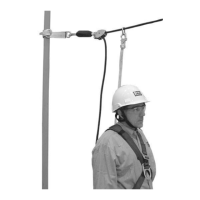
When the victims position is reached, descent can be interrupted by rmly grasping and holding the free end
of the rope (see Figure 10). If a secondary rescuer is available at the R550 Device, the free end of the rope can be
passed through the pigtail and then secured in the cam cleats to prevent unintentional descent while the primary
rescuer is securing the victim.
2. Connect the Victim to the R550 Device: Connect a rescue lanyard (RL) (or similar equipment) between the lifeline
snap hook connected to the rescuer’s full body harness front D-ring (RD) or the back D-ring on the victim’s full body
harness (C).
;
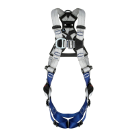
Do not use a body belt with this equipment. Body belts do not support your entire body, which may result in
serious injury.
3. Disconnect the Victim’s Fall Arrest Subsystem: Ensure that the victim is securely attached to the R550 Device
and then detach the victim’s fall arrest subsystem (lanyard, etc.) to free the victim for descent.
;
If a secondary rescuer is available at the R550 Rescue & Escape Device, the Rescue Hub can be used to raise
the victim slightly for detachment of their fall arrest subsystem.
4. Descend to Safety: Release the free end of the lifeline to initiate descent. Descent speed will be automatically
controlled to a rate described in Table 1 by the R550 Device’s centrifugal brake. Descent may be interrupted by rmly
grasping the free end of the lifeline (see Figure 10). Bend your knees to prepare for landing. After landing, disconnect
the lifeline from the body support. Record all descents in the Descent Log (Table 3).
;
The R550 Device may become hot during use which could injure the user if parts other than those used to
control the descent are touched. Use beyond the specied load and descent length limits may generate excessive
heat which could damage the descent line.
4.3 AFTER A RESCUE: The R550 Device must be removed from service following use in a rescue event. The R550 Device
should then be destroyed or sent to an authorized service center for inspection and repair. See Section 5.3 for more
information.
5.0 INSPECTION
;
After product has been removed from service, it may not be returned to service until a Competent Person
conrms in writing that it is acceptable to do so.
5.1 INSPECTION FREQUENCY: The R550 Device must be inspected at the intervals dened in Section 1. Additionally, the
R550 Device must be sent to an authorized service center for inspection and service every ve years. See Section 5.3
for more information. Inspection procedures are described in the “Inspection and Maintenance Log” (Table 2). Inspect
all other components of the Fall Protection System per the frequencies and procedures dened in the manufacturer’s
instructions.
;
Humidity Resistant Case Inspection: If the R550 Device is stored continuously in a Humidity Resistant Case (see
Figure 12), monthly and yearly inspections are not required and the device may be sent to an authorized service center
at intervals not to exceed ten years. In addition to inspection prior to each use, the Humidity Indicator on the case (see
Figure 12) should be inspected annually and the date and inspector’s initials logged on the Case Inspection Label. If the
Humidity Indicator displays a reading of 60 or greater (Pie Sector Indicator), the case should be removed from service
and the contents inspected per the procedures dened in the “Inspection and Maintenance Log” (Table 2).
5.2 DEFECTS: If inspection reveals an unsafe or defective condition, or if any doubt should arise as to its condition for safe
use, remove the R550 Device from service immediately and label “DO NOT USE”. Do not attempt to repair the device.
5.3 RECERTIFICATION: After it has been removed from service, or at least every ve years (excluding humidity resistant
case storage), the R550 Device must be sent to an authorized service center for thorough inspection, maintenance, and
recertication.
5.4 PRODUCT LIFE: The functional life of the R550 Device is determined by work conditions and maintenance. As long as the
product passes inspection criteria, it may remain in service.
 Loading...